[:es]El propósito de esta entrada es indicar los pasos necesarios para lograr hacer un diseño CAD muy básico para representar un servo de 360º FS90R colocado justo debajo de la base del robot DYOR.
Nuestro objetivo de diseño es lograr obtener un diseño CAD para un servo de 360º FS90R. Los servos están colocados en la parte trasera, justo debajo de la base del robot, no requiriendo ningún orificio para su sujeción, ya que irán pegados. Por tanto, utilizaremos la capa de grabado superficial para dibujar la forma del servo (aunque irá pegado por debajo, la serigrafía quedará en la parte de la cara de arriba de la base. El resto de elementos a dibujar son puramente decorativos y por tanto irá en la capa de anotaciones.
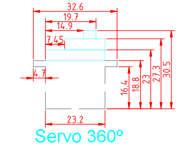
La medidas del servo son como se muestra a continuación:
A partir del fichero de plantilla para los componentes:
Dibujamos la forma del servo (desde la esquina de la oreja izquierda), seleccionando la capa de «Grabado Superficial»:
polyline
0,18.8
@-4.7,0
@0,-2.4
@4.7,0
@0,-16.4
@23.2,0
@0,16.4
@4.7,0
@0,2.4
@-4.7,0
Ahora en la capa de «Anotaciones», vamos a crear tres elementos rectangulares:
rectangle
0,18.8
23.2,23
rectangle
7.45,23
23.2,27.3
rectangle
14.9,27.3
19.7,30.5
Finalmente podéis escribir un texto seleccionando la herramienta «Texto» del menú de herramientas (a la izquierda) para identificar el dibujo. Seleccionad la letra y tamaño de fuente conforme creáis conveniente (nosotros utilizamos Arial tamaño 5). También podéis añadir cotas, seleccionando la capa de Cotas, y utilizando las «Herramientas de dimensión» del menú de herramientas.
Aquí podéis descargar el fichero DXF con la solución:
[:en]The purpose of this entry is to describe necessary steps to design a basic CAD model of a 360º servo, based on FS90R, that will be placed at the bottom of the base of DYOR Robot.
Our aim is to design a CAD design of a 360º servo (continuous rotation servo) that they are usually placed at hte bottom of the robot’s base. The motors will be glued to the base, so there’s no specific hole required to support it, then all design elements will be drawn in the Auxiliary layer.
The servo measurements are shown below:
We will use the following template:
Let’s start by drawing the servo shape (starting from the ear at the left side) and select the Auxiliary layer:
polyline
0,18.8
@-4.7,0
@0,-2.4
@4.7,0
@0,-16.4
@23.2,0
@0,16.4
@4.7,0
@0,2.4
@-4.7,0
Now, draw three rectangles:
rectangle
0,18.8
23.2,23
rectangle
7.45,23
23.2,27.3
rectangle
14.9,27.3
19.7,30.5
Finally, we can some text and dimensions.
Here you can find the solution:
[:]