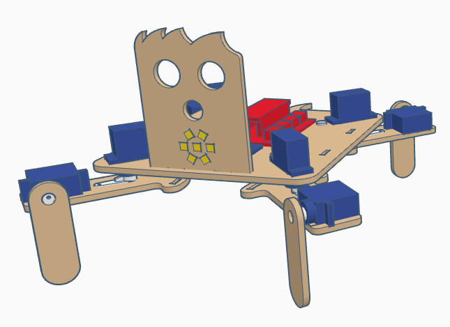
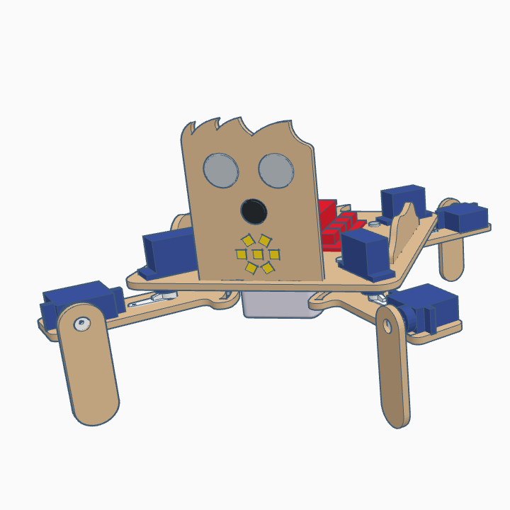
[:es]En esta entrada os mostramos el ensamblaje del robot DYOR qPED realizado con TinkerCAD y fabricado con corte láser.
Componentes:
- Arduino Nano + Shield Arduino Nano I/O (rojo)
- Powerbank (blanco)
- Ultrasonido HC-SR04 (gris claro)
- Zumbador de sonido (negro)
- Servo SG90 (azul oscuro)
- Tira de LEDs redonda (amarillo)
- Bluetooth (azul oscuro)
Instrucciones
Posicionar los servos en 90º para poder atornillar las manillas correctamente posteriormente. Este robot dispone de cuatro patas con dos piezas por patas que se denotarán como piezas de las patas a las que están en contacto con el suelo y piezas de la cadera a las que unen la base del robot con las piezas de las patas.
Antes de empezar, aseguráos que las manillas de los servos están bien pegadas en los huecos correspondientes del las piezas de las caderas y patas del robot.
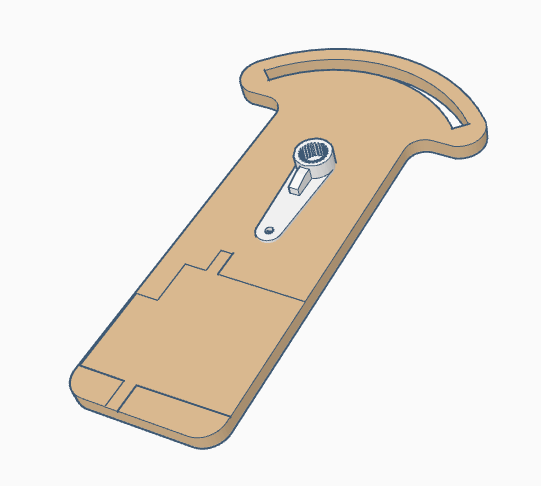
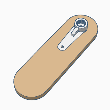
Pegar los servos de las patas en cada una de las piezas de las caderas. Fijaos en el dibujo grabado para la posición correcta del servo, ya que hay dos posibles configuraciones. Los ensamblajes de las patas delanteras y traseras son idénticos, con lo que se mostrará sólo el ensamblaje de dos de las patas delanteras.
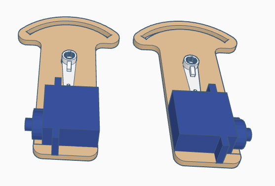
Atornillar la manilla del servo pegada a la pieza de la pata al servo de la pata. La configuración mostrada debería corresponder a la configuración de 90º que tomaremos por defecto.

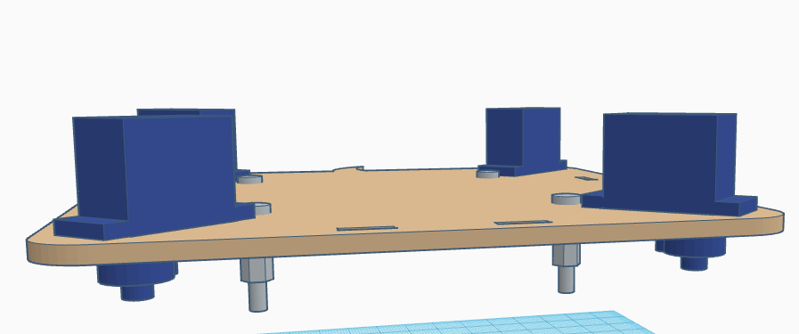
Pegar los cuatro servos de las caderas a la base del robot con los ejes apuntando hacia abajo y lo más cerca posible de las esquinas de la base.
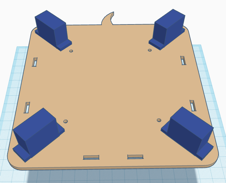

Atornillar los tornillos de M3 al separador en los orificios redondos de la base.
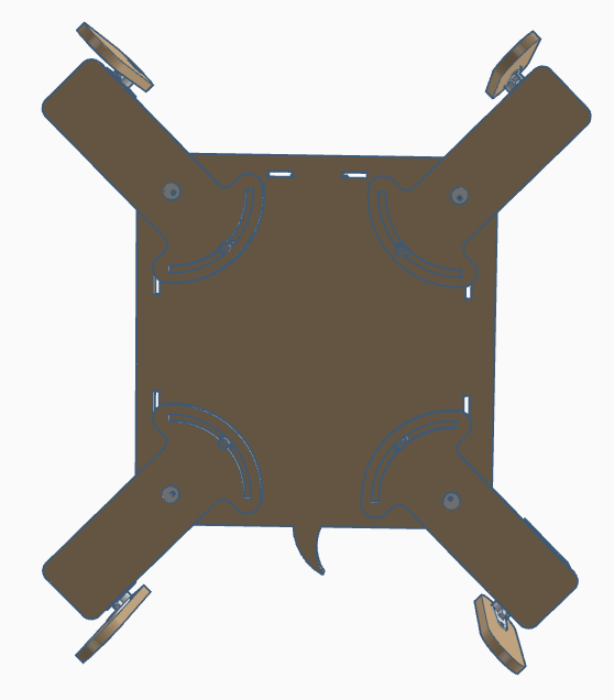
Ahora, desde la cara de abajo, debemos fijar la manilla de los servos de las caderas asegurándonos que el «macho» del separador está dentro de la ranura de la pieza de la cadera. Fijaos bien en el montaje de las patas de forma que siempre quedan en la parte interior de las extremidades (tanto los de delante como los de detrás).
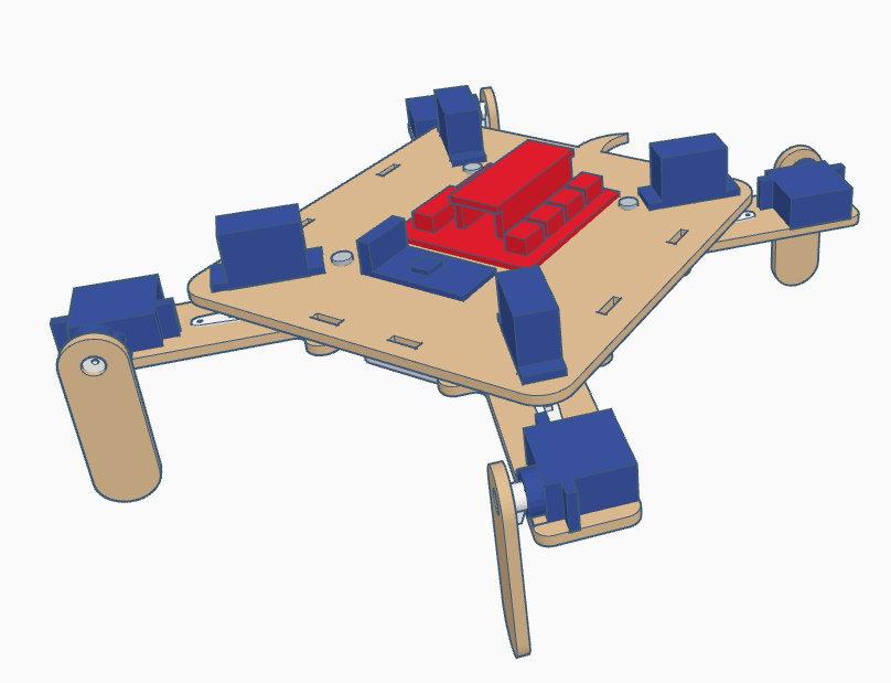
Pegar la electrónica de Arduino y el módulo bluetooth en la cara superior del robot. Aseguráos que el conector USB del Arduino Nano v3.0 está accesible desde la parte trasera del robot.
Pegar el frontal del robot.
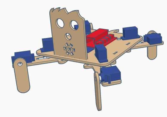
Pegar la tira de LEDs redonda asegurándonos que tenemos soldados los cables antes de pegarla.
Ahora pegaremos el zumbador de sonido.
y el sensor de ultrasonidos HC-SR04 con los pines de conexión apuntando hacia arriba.
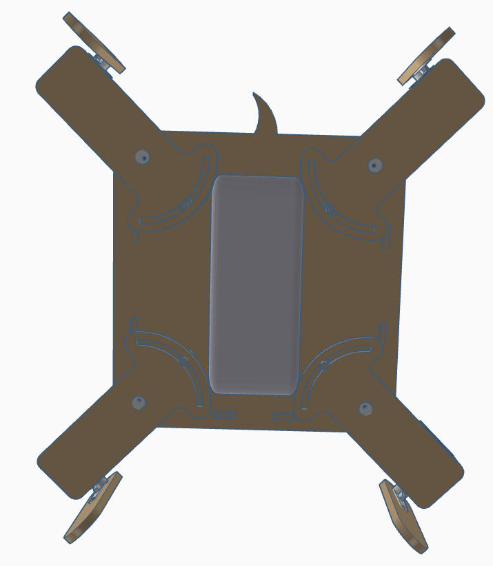
En la parte de debajo del robot pegaremos el Powerbank. Este elemento debería entrar justo en el hueco de en medio de las piezas de las caderas del robot, con lo que al pegarlo aseguráos que ninguna de estas piezas colisiona con él.
Finalmente, añadiremos los elementos decorativos en los laterales.
[:en]In this entry, we show the assembly of DYOR qPED in TinkerCAD for laser cutting manufacturing.
Components:
- Arduino Nano + Shield Arduino Nano I/O (red)
- Powerbank (white)
- Ultrasound HC-SR04 (light gray)
- Buzzer (black)
- Servo SG90 (dark blue)
- Rounded LED strip (yellow)
- Bluetooth (dark blue)
Instructions
Make sure that the servos at positioned at 90º before you screw the servo horns to the axis. The robot has four legs, with two parts par each leg that will be denoted as «leg part» the one being in contact to the ground and «hip part» as the one joining the robot base and the «leg part».
Before starting, glue the servo horns to the «hip parts» and «leg parts»
Glue servo legs to each of the «hip parts». Take into account the line engraving of each part to properly place the servos. The are two possible configurations for the left and right, so pay attention. The assembly of the front and rear legs are identical, so we will only show the assembly of the front ones.
Screw the servo horns of the «leg parts» to the servos that have just been glued to the «hip parts». Make sure that the configuration of the legs is as shown, since this will be considered as the home configuration.
Glue the four servos of the hips to the robot base, with the axis pointing downwards and as close as possible to the corner.
Screw the M3 screws to the M3 spacers through the round holes at the robot base.
Now, from the bottom side, we must screw the servo horns to the hip servos with the «male» connector of the M3 spacer passing through the corresponding hole of the «hip part». Take into account that the robot’s legs are always at the inner side of the legs.
Now, glue the Arduino electronics and the bluetooth module on the robot’s base.
Also, glue the robot’s face.
And the rounded LED strip to it (it requires to solder the cables to the pins first).
After that, we can glue the buzzer
and the ultrasound snesor with the pins pointing upwards.
Again, in the bottom side we must glue the powerbank. The space withing the «hip parts» is narrow, but it should fit inside (make sure that it does not collide with any «hip part»).
Finally, we will add the decorative elements on the sides.
[:]