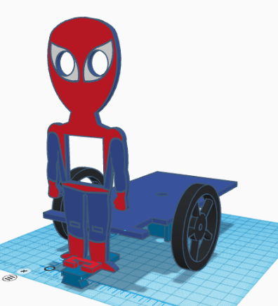
[:es]En esta entrada os mostramos el ensamblaje del robot DYOR SpiderBot realizado con TinkerCAD y fabricado con corte láser
Componentes:
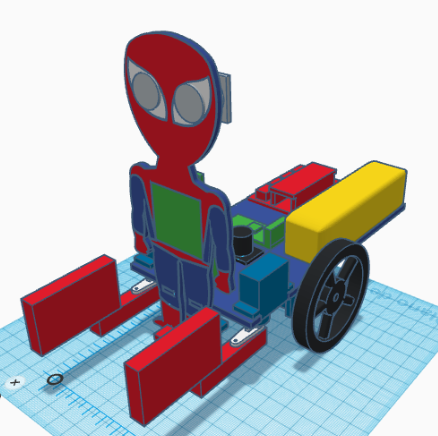
- Arduino Nano + Shield Arduino Nano I/O (rojo)
- Powerbank (amarillo)
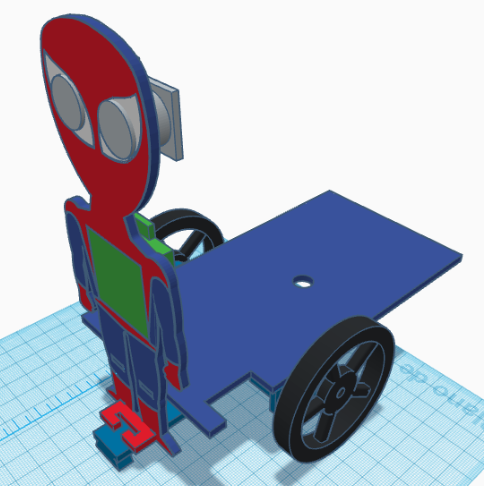
- Ultrasonido HC-SR04 (gris claro)
- Zumbador de sonido (negro)
- Servos SG90 (azul oscuro) en el frontal
- Servos FS90R (azul oscuro) en la base
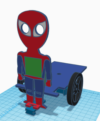
- Bluetooth (verde)
- Seguilíneas TCRT5000 (azul oscuro)
- Rueda loca (blanco)
- Ruedas FS90R (negro)
- Matriz de LEDs (verde)
- Piezas de LEGO (rojo)
Instrucciones:
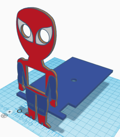
Colocar la pieza del frontal junto con la base y pegarlas.
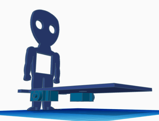
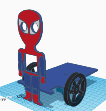
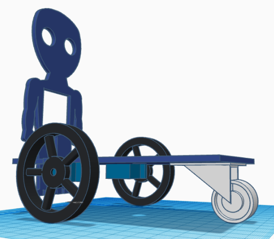
Pegar los servos FS90R a la base, estando el eje lo más atrás posible y atornillar las ruedas.
Pegar la rueda loca en la parte trasera de la base
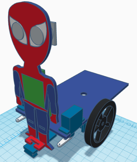
Pegar el soporte del sensor TCRT5000 en los pies de forma horizontal y pegar el sensor al soporte (por debajo).
Pasar los cables, tanto de los servos FS90R como del sensor TCRT5000 por el orificio que tiene la base. Una vez pasados los cables, podremos pegar la matriz de LEDs al frontal con los cables de conexión por la parte inferior.
Pegar el sensor de ultrasonidos
Pegar los servos SG90 de posición apuntando hacia abajo en los orificios correspondientes de la base. El eje del servo debe de estar lo más adelantado posible. Las manillas de los servos, deben atornillarse de forma que la posición mínima esté justo apuntando hacia las piernas del frontal.
Pegar ahora las piezas de LEGO a las manillas del servo.

Pegar la electrónica de Arduino, el Powerbank, el módulo bluetooth y el zumbador de sonido a la base.
Vídeo
[:en]In this entry, we show the assembly of DYOR SpiderBot with TinkerCAD and make with laser cutting
Components:
- Arduino Nano + Shield Arduino Nano I/O (red)
- Powerbank (yellow)
- Ultrasound HC-SR04 (light grey)
- Buzzer (black)
- Servos SG90 (dark blue) in the frontal face
- Servos FS90R (dark blue) in the base
- Bluetooth (green)
- Linetracker TCRT5000 (blue)
- Caster wheel (white)
- FS90R wheels (black)
- LED Matrix (green)
- LEGO parts (red)
Instructions:
Glue both parts, the base and the frontal face.
Glue the FS90R servos to the base, the servo axis has to be as far as possible to the frontal face and screw the wheels to the servos.
Glue the caster wheel to the base
Glue the TCRT5000 support just below at the feet and glue the TCRT5000 sensor to the support (glue it so the sensor is below the feet horizontally).
FS90R servo cables and TCRT5000 cables can be now pass through the base hole. After that, we can glue the LEDs matrix to the frontal face (cables pointing downwards).
Glue the ultrasonic sensor HC-SR04
Now, glue the SG90 servos, with the axis pointing downwards. The servos are located at their corresponding holes at the base. The servo horn must be screwed to the servo axis so that the minimum position is pointing to the legs (to avoid collision).
Glue the LEGO parts to the servo horn
Finally, glue the Arduino electronics, Powerbank, buzzer and Bluetooth module to the robot base.
[:]