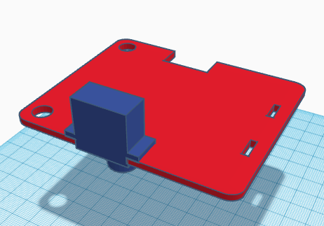
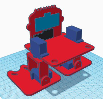
[:es]En esta entrada os mostramos el ensamblaje del robot DYOR bPED básico realizado con TinkerCAD para impresión 3D.
Componentes:
- Placa Arduino Nano I/O + Arduino Nano v3 (arena)
- Soporte para batería de 9V (negro)
- Ultrasonido HC-SR04 (azul claro)
- Zumbador de sonido (negro)
- Servos SG90 (azul oscuro)
- Rodamiento y remache
Instrucciones:
Distinguiremos entre los servos de los pies, que están junto a los pies, de los servos de las piernas que están en la propia base del robot. También haremos diferencia entre la manilla simple que necesitan los servos de los pies y la manilla doble que necesitan los servos de las piernas.
IMPORTANTE: Para el montaje del robot, los servos deben estar colocados en posición de 90º antes de realizar el ensamblaje, para que el robot sepa que esa es la posición de «Inicio». El siguiente programa os permitirá posicionar los servos en 90º (conectándolos a los pines correspondientes).
Comenzar el montaje por las piernas, insertando servo de la pierna en el agujero de la base apuntando el eje hacia abajo.
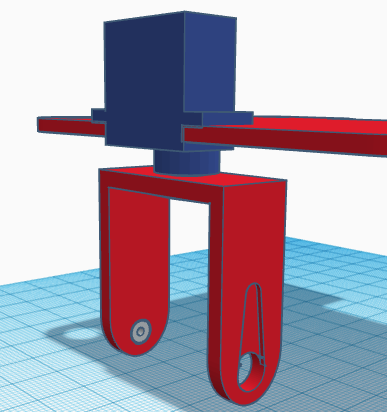
Recortaremos la manilla del servo de la pierna para que entre en el hueco de la pieza de la pierna en la parte interior y atornillaremos la manilla al servo. Atornillar con cuidado para que no gire el eje colocando la pierna recta según se indica en el ensamblaje. Una vez atornillado, es conveniente no mover manualmente la pierna, ya que el servo podría dañarse.
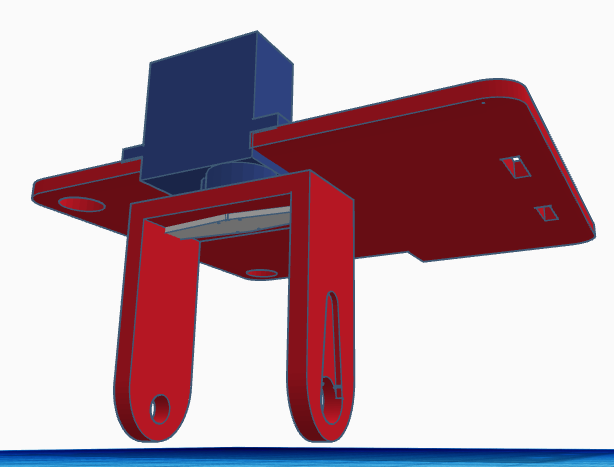
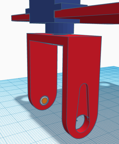
Introducimos el rodamiento en el agujero correspondiente para el tobillo.
Introducir el remache por el eje del rodamiento.
Introducir el servo del pie dentro del hueco de la pierna de forma que podamos atornillar la manilla (simple) del servo al eje. La manilla se coloca por la parte exterior de la pierna. Atornillar con cuidado para que no gire el eje colocando el servo en la posición indicada en el ensamblaje.
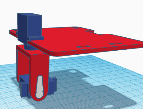
Una vez colocado y atornillado el servo, deberemos pegar el servo al pie, fijándonos bien que la posición sea la correcta.
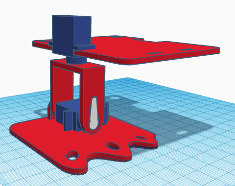
Repetir el procedimiento anterior para el otro pie.
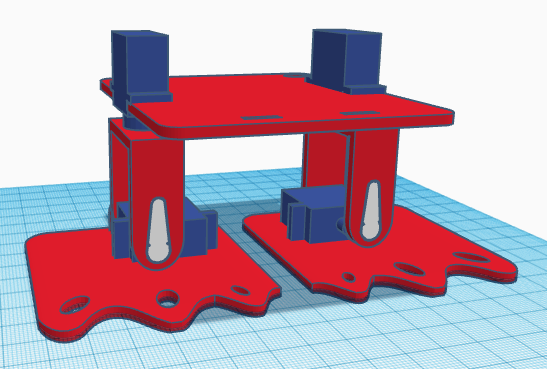
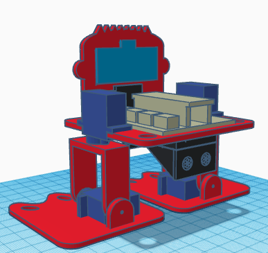
El sensor de ultrasonidos y el zumbador se pegan directamente a la cara del robot y ésta a su vez se inserta dentro de los orificios de la base y se pega a ella.
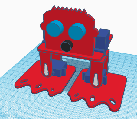
La electrónica y el portapilas se pegan también a la base. La electrónica se pega en la cara superior, mientras que el portapilas podemos pegarlo en la cara inferior.
 [:en]In this entry, we show the assembly of DYOR bPED Basic designed with TinkerCAD for 3D Printing.
Components:
- Arduino Nano I/O Shield (sand)
- Battery holder (black)
- Ultrasound HC-SR04 (light blue)
- Buzzer (black)
- SG90 Servos (dark blue)
- Ball bearing and rivet
Instructions:
We will distinguish between the servos required for the feet and the servos required for the legs. Also, we will distinguish between the servo horns required for the feet and the ones required for the legs.
We will distinguish between the servos required for the feet and the servos required for the legs. Also, we will distinguish between the servo horns required for the feet and the ones required for the legs.
IMPORTANT: When assembling the robot, the servos must be in 90º position, so that the «Home» configuration is the one shown in the assembly. The next program will allow you to position the servos at 90º (connecting them at the right pins).
First, pass the servo through its corresponding hole at the base (pointing downwards) and with the axis centred.
Now, we need to fix the leg servo with its servo horn (double-sized). The servo horn must be cut at the ends so that it fits inside the leg. When screwing the horn, be careful in not rotating the servo axis. Once is fixed, it is not recommended moving the leg since the motor can be damaged.
Afterwards, we need to assemble the legs by inserting the ball bearing for the ankle at the corresponding hole.
The rivet will be inserted from the inner side of the leg so that once we put inside the leg the foot servo, the rivet doesn’t fall apart.
Now, screw the servo to the horn (simple). Make sure you place the servo at the correct orientation (as shown in the assembly). The servo horn will be visible from the front side. Be careful in not rotating the servo before screwing it.
Once fixed, we can glue it to the foot.
Repeat this procedure to assemble the other foot.
The ultrasound sensor and buzzer are glued directly to the robot’s front. The robot’s front is also glued to the base.
The electronics and battery holder are also glued to the base. The electronics is glued on top, while the battery holder is glued under.
[:]