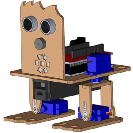
[:es]En esta entrada se describe el ensamblaje del robot DYOR bPED (por corte por láser).
Piernas y pies del robot
1. Pegar el tobillo al pie del robot.

2. Insertar el rodamiento en la pieza de la parte trasera de la pierna e insertar el remache en el agujero del talón.
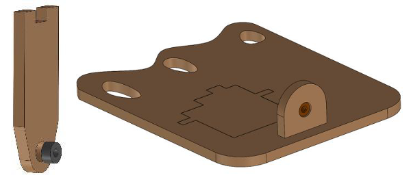
3. Pegar la punta del remache y pegarlo al cojinete.
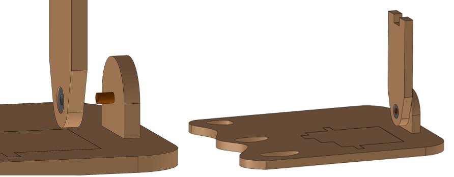
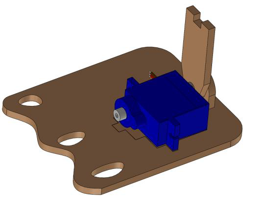
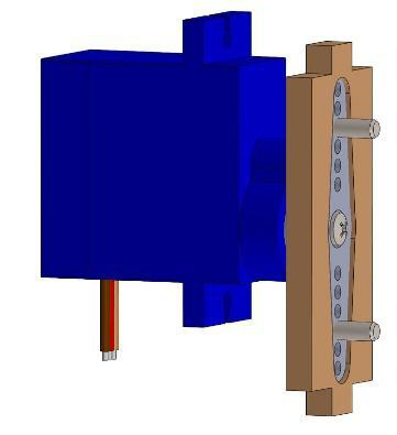
4. Pegar el servo al pie
5. Colocar la manilla en la pieza de la parte delantera de la pierna y fíjala con un tornillo o simplemente pégala.
6. Atornilla la manilla al eje del servo del pie

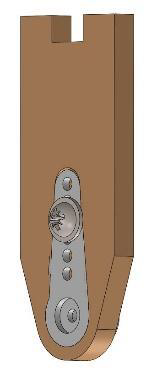
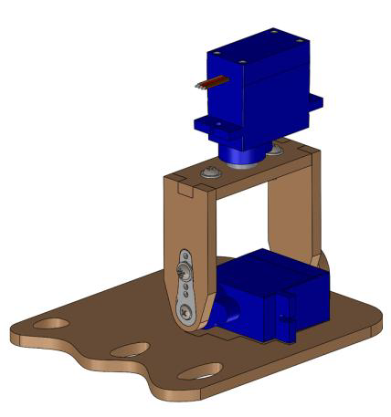
7. Coloca la manilla doble del servo de la pierna en la pieza superior de la pierna (atornilla la manilla o pégala con pegamento).

8. Atornilla el servo a la manilla.
9. Pega la pieza de la parte superior de la pierna a las piezas del pie y la pierna que ya disponéis.
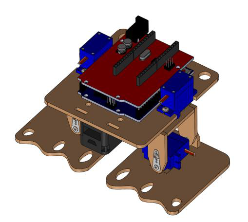
Cuerpo
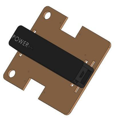
1. Fija el powerbank a la parte interior de la base del robot, ya sea con bridas o simplemente pegándolo.
2. Pega la electrónica (ESP32) a la base del robot con pegamento termofusible.
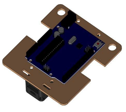
3. Coloca la tarjeta de expansión de Arduino Nano I/O encima de la electrónica.

4. Monta la base y las piernas. Fija los servos de las piernas con tornillos o simplemente pégalos a la base.
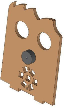
Cara
1. Conecta primero los cables del sensor de ultrasonidos, zumbador y tira de LEDs para asegurarse que cuando los montes tienes espacio suficiente.
2. Pega el zumbador con los cables conectados con pegamento termofusible.
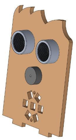
3. Pega el sensor de ultrasonidos a la cara con pegamento termofusible.
4. Pega la tira de LEDs a la cara con pegamento termofusible o atorníllala.
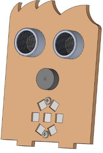
5. Pega la cara al cuerpo del robot.
Video
[:en]In this entry, we describe the assembly of DYOR bPED (manufactured with Laser cutting).
Legs and feet
1. Glue the ankle to the robot’s foot.
2. Insert the ball bearing inside the hole of the back-side leg part and insert the rivet inside the ankle’s hole.
3. Glue the tip of the rivet to the ball bearing.
4. Glue the servo to the feet.
5. Insert the servo horn inside the front-side leg part and screw it or simply glue it.
6. Screw the servo horn to the servo axis.
7. Insert the servo horn (long shape) inside the top-side leg part and screw it or simply glue it.
8. Screw the servo horn to the servo axis.
9. Glue the top-side leg part to the remainder of parts that you have already assembled.
Body
1. Glue the Powerbank to the robot base. You can alternatively, fasten some stripes to it too.
2. Glue the electronic board to the other side of the base.
3. Also, attach the Arduino Uno Sensor Board to the electronic board.
4. Assemble the base and the legs altogether, by screwing the servos or simply glueing them.
Face
1. Connect first the cables for the ultrasonic sensor, buzzer and LED’s strip to make sure you have enough space.
2. Glue the buzzer to the face laser cut part.
3. Glue the ultrasonic sensor (with pins pointing upwards).
4. Glue the LEDs strip.
5. Glue the robot’s face to the base.
[:]