[:en]This post presents the ElectRick bot, an ESP32-based, two-wheeled mobile robot which can be controlled via an Android app. It features a manual driving mode, a line following mode and an obstacle avoidance mode.
Content of the project folder:
- 3D Model (STEP format, 3D-printed parts as STL)
- ESP32 Code (.ino, .h and .cpp files)
- Android app (.apk and .aia project file)
- Bill of Materials
- Wiring Overview
Used Programs/Tools:
- SolidWorks Student Edition 2023 SP2.1
- Arduino IDE 2.3.2
- MIT App Inventor (https://appinventor.mit.edu/)
Parts selection
The project started with the wish to use DC motors instead of servo motors in order to allow the robot to go faster. Another central decision made early on in the project was to utilize an ESP32 rather than an Arduino due to its integrated WiFi/Bluetooth capability. Based on these initial decisions, I arrived at the parts detailed in the bill of materials. The robot is powered by a 9V battery supplying both the ESP32 and the motors and the electronics are mounted to a central body using custom 3D-printed parts, ensuring good structural stability.
Motor Control
A central problem in the design of the robot was the control of the DC motors. The L298n motor driver which was chosen for this build, uses a dual full-bridge driver in order to control both the polarity and the level of the voltage supplied to the motor pins. Using a 3.3V PWM signal from the ESP32, it is possible to apply any voltage between -7V and 7V to each of the motors (considering the drop of approx. 2V over the L298n circuitry). The motors’ nominal voltage is 6V, meaning that the motors have to be protected from overvoltage by imposing a software limit on the maximum duty cycle of the PWM signal used to control the motor voltage.
Instead of simply applying a voltage though, we want to be able to control the rotational speed of the motors. First experiments showed that the motors do not start rotating until about 2-3V are applied from which point on the rotational speed is roughly proportional to the additional voltage. This means the motor behavior can be approximated with a dead zone non-linearity as shown below (the input is the motor voltage and the output is the motor’s angular velocity).
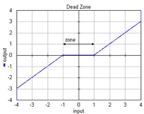
This approach is sufficient for manual driving. However, it fails when accurate motor speeds are required. The big flaw in this model is that in reality, the motors do not start spinning slowly and instead jump into motion when the torque overcomes the static friction. This makes driving at slow speeds difficult and means that the same voltage applied to the motor pins may result in different rotational speeds depending on whether you start from a standstill or not.
The solution I chose was to measure the motors’ rotational speed using optocouplers (which essentially function as incremental encoders). Slotted interruptor discs mounted to the motor shaft interrupt an optical path 20 times per full rotation which registers as pulses on the signal pin of the optocoupler. The hardware counters of the ESP32 can count these pulses without having to use interrupts in the program, allowing a periodic reading of the pulse count registers instead. By calculating the number of pulses divided by the time interval (and smoothing the values with a moving average filter) the motor’s rotational speed can be obtained. Since the wheels are mounted directly onto the motor shaft, the motor’s angular velocity translates one to one to the wheel’s angular velocity. Due to the use of only one interruptor disk per motor, the optocoupler signal cannot tell us the rotational direction of the wheel. This can be worked around by having the polarity of the motor voltage determine the rotational direction of the wheel.
The last step in controlling the motor speed is the implementation of the closed loop control. From previous experience with DC motors, a PI feedback controller seemed appropriate wile also not adding too much complexity. For every control step, the microcontroller calculates the rotational speed of the wheel and its deviation from the target speed. A weighted sum of the current deviation and the discrete integral of the deviation over time is calculated and used to determine the voltage supplied to the motor. The coefficients of the PI controller are subject to tuning and can dynamically be changed inside the app without reflashing the ESP32.
Robot functionality
Android App
The app is divided into four different interfaces: The PI Control panel, the Manual mode interface, the Line Following mode interface and the Obstacle Avoidance mode interface. The UI element sizes are chosen for the screen of a Samsung Galaxy A71 and will need to be adjusted on other devices. You can change between the interfaces by pressing their respective buttons on the app screen. The top row of elements containing the device list, Connect/Disconnect button and Connection Status display are shared between all four different interfaces.
PI Control
The PI control panel allows the user to switch between open and closed loop control of the motors. If «PWM» is enabled, the duty cycle of the motor signal is set directly (according to the previously discussed dead zone non-linearity model). If «PI-Control» is enabled, the motors are instead controlled with a feedback loop applying a PI controller. The parameters K_p and K_i are the proportional and integral gain for the motor speed control and impact the control behavior. The grey bar at the top of the panel shows the values currently set on the ESP32 as well as the enable status of the PI control. The control type chosen in this interface carries over to all other modes.
Manual mode
The manual mode allows the user to use a joystick to drive the robot. As the robot’s configuration prevents it from moving sideways on the spot, the left to right movement of the joystick instead makes the robot turn. In this mode, the app displays the current x,y-position of the joystick (Horizontal, Vertical), the rotations per minute of each of the wheels (ω_L, ω_R) as well as the rotational angle of the robot base (φ_z). The z-axis rotation of the robot is obtained by integrating the angular acceleration data obtained from the 9-axis motion sensor (MPU9250) located at the front of the robot.
Line following mode
In the line following mode, the robot uses its TCRT5000 infrared sensor to follow a line marked with black tape. The line following sensor is mounted below the main body at the front of the robot. Its mounting height as well as its sensitivity can manually be adjusted. The app interface also allows the user to set the robot’s forward driving speed (in % of max. speed), the proportional constant K_line determining how strongly the robot corrects deviations from the line and the sensor output value when the robot is perfectly over the edge of the line («Grey»). In order to not have the robot start driving immediately when switching to this mode, the on-off switch at the bottom activates and deactivates the motors. The displayed values at the top of the panel are the current sensor value of the TCRT5000 («Sens»), the currently set speed («Speed») and the rotational angle of the robot base (φ_z).
Obstacle avoidance mode
In the obstacle avoidance mode, the robot relies on its three IR distance sensors located at the front to stay clear of obstacles and change its direction when encountering objects. This mode is based on a rather simple state machine in which robot drives in a straight line until it detects an object ahead. At this point it stops and turns by a predefined angle towards the left or right, depending on whether or not the sensors on the side have detected an object as well. Once the turn angle has been exceeded and the way ahead is clear, the robot briefly stops again and then starts driving in the new direction. Through the app, the speed when driving straight and turning can be set individually and the turn angle can be modified. The app also displays the current state (0: driving straight, 1: turning left, 2: turning right), the robot angle at the start of the turn (φ_init) and the current robot angle (φ_z). Moreover, it allows disabling/enabling the motors similar to the line following mode.
Difficulties and further improvements
Battery
One of the main problems of this build was the power supply of the robot. The robot kit with the motors and wheels originally included a battery socket for 4xAA batteries, supplying a voltage of 6V. This proved to be too low of an input voltage for the ESP32 which needs 7-12V so a design change towards a 9V battery had to be made. While this was enough to power all the electronics, a single 9V battery did not last a very long time. The typical current drawn by the entire robot at maximum speed was measured to be about 300mA, with current spikes reaching even higher values.
The rapid draining of the battery leads to a declining supply voltage. For the ESP32 development board which has an on-board voltage regulator, this is not an issue. However, it means that the effective voltage supplied to the motors by the battery decreases over time, even while the duty cycle remains identical. As a consequence, tuning the motor controller and the robot behavior, is very hard, because the system keeps changing.
In future projects using a similar set of motors, the use of a Lithium Polymer (LiPo) battery with a voltage stabilizer should be considered. Though more expensive, it would extend the operation time, offer the ability to recharge the battery and stabilize the supply voltage thus eliminating the system’s dependency on the charging level of the battery.
IR Distance Sensors
The orientation of the sensors was initially chosen based on the idea of being able to navigate a simple maze with only right angles. However, for dynamic obstacle avoidance in an unstructured environment, the sensors on the sides should preferrably be angled more towards the front to avoid driving into smaller objects that do not get detected by the central, front-facing sensor.
It is also worth considering changing out the IR distance sensors altogether. In its current form, they can only detect whether an object is present or not and their range is rather limited. Alternative sensors worth considering are ultrasonic sensors or Sharp distance sensors, both of which would be able to give an analog distance measurement.
Off-Center Kinematics
The robot’s ability to control its wheels’ velocities and sense its rotation about the central axis in theory make it suitable for off-center kinematic control. Based on an off-center kinematic model, a specified point on the robot could follow a predefined trajectory or be steered in any direction with the joystick in the app. The quality of the components will pose limits to the accuracy of the robot movement, but this possible improvement does not require hardware changes and would therefore be easy to test.