[:es]En esta entrada se explica el procedimiento para diseñar en TinkerCAD el robot DYOR bPED.
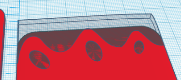
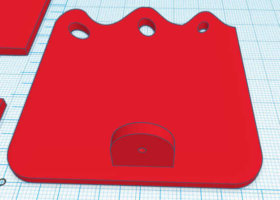
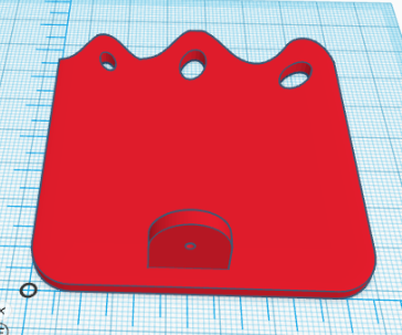
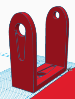
El resultado esperado tras seguir los pasos de esta entrada es como el que se muestra:
Primero descargaremos los ficheros STL que necesitaremos para crear los huecos de algunos componentes.
Diseño de la base
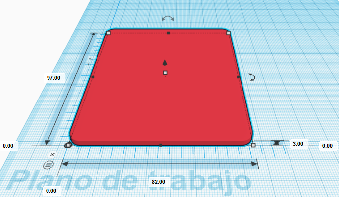
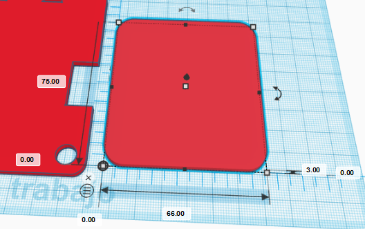
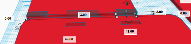
Empezaremos añadiendo una regla a nuestro entorno de trabajo. Colocadla próxima a la esquina inferior izquierda del espacio de trabajo. Después, creamos un cubo de dimensiones (82,97,3) mm y lo posicionamos en la coordenada (0,0,0) mm con respecto de la regla. También modificamos la propiedad «radio» a 1.22 mm para redondear las esquinas de la base (aproximadamente unos 5mm reales de radio de redondeo).
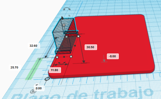
Importar el fichero «Servo.stl» y posicionarlo en la coordenada (0,25.7,-13) mm, girarlo 180º de forma que apunte hacia abajo y establecer que tiene forma hueca.
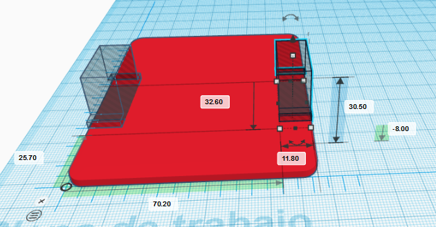
Ahora repetimos el procedimiento y posicionamos otro servo en la coordenada (70.2,25.7,-8) mm, también apuntando hacia abajo y estableciendo que tiene forma hueca.
Ahora creamos un cilindro hueco de dimensiones (9,9,3) mm y lo posicionamos en la coordenada (3.5,3.5,0) mm que permitirá pasar los cables de los servos de la pierna izquierda.
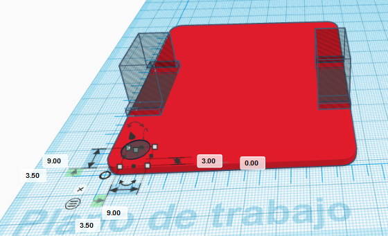
De igual manera, creamos un cilindro con las mismas dimensiones posicionado en la coordenada (69.5,3.5,0) mm para que pasen los cables de los servos de la pierna derecha.
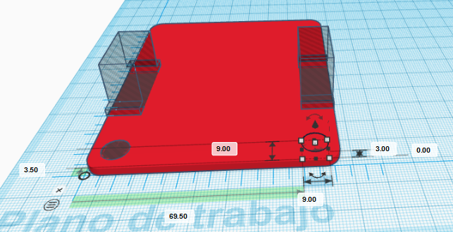
Ahora, para los orificios que soportarán la cara del robot, creamos dos cubos huecos de dimensiones (10,3,3) mm posicionados en las coordenadas (22,89,0) mm y (50,89,0) mm, respectivamente.
Finalmente, agrupamos todas las formas creadas para la base para generar la pieza a imprimir.
Diseño de los pies
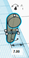
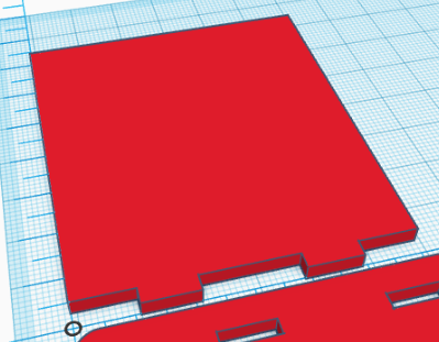
Ahora desplazamos la regla hacia la derecha, donde empezaremos a crear un pie del robot. Si es necesario, se puede desplazar la pieza de la base hacia la izquierda para que no interfiera con la nueva pieza. Para el diseño del pie izquierdo, crearemos un cubo de dimensiones (66,75,3) mm posicionado en la coordenada (0,0,0) mm con un radio de redondeo de 2.44.
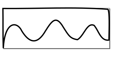
Para generar los dedos de los pies utilizaremos una función avanzada de TinkerCAD en combinación con un dibujo hecho en Inkscape. El objetivo es generar un forma que posteriormente eliminaremos del cubo utilizado para el pie.
Primero, debemos dibujar en Inkscape una curva Bézier que de forma aproximada genere esta forma con tamaño 66×25 mm (aseguraos que trabajáis en mm):
El fichero utilizado para este dibujo lo podéis descargar aquí:
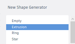
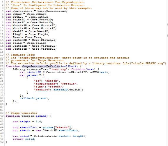
Después, debemos en TinkerCAD generar nuestra propia forma, en este caso debemos seleccionar una extrusión (quiere decir que a partir de una geometría 2D generaremos una geometría 3D elevándola una altura determinada). Seguid las instrucciones tal y como se muestran:
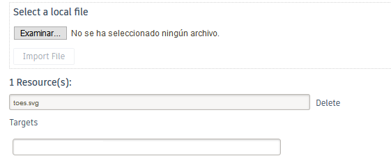
Una vez en el generador de formas, por defecto aparece una geometría correspondiente a un círculo. En la parte de la izquierda, podemos administrar los «recursos» de nuestra forma. Si accedermos a «resources», podemos borrar la geometría que aparece por defecto e importar la geometría creada en el fichero «toes.svg» con la forma de los dedos o cualquier otro dibujo que consideremos apropiado.
Por algún tipo de incompatibilidad, TinkerCAD no reconoce correctamente las unidades por defecto. Por este motivo, debemos ir al fichero recién importado, aparecerá justo debajo de «resources» y en las líneas que aparece width=»66mm» y height=»25mm», debemos reemplazarlas por width=»66px» y height=»25px», respectivamente.
Ahora, en el fichero «main.js» podemos modificar el aspecto de la geometría a crear simplemente reemplazando el nombre ‘circle-2RL4RC.svg’ por ‘toes.svg’ dentro de la función «shapeGeneratorDefaults» y la línea «var height = 20.0;» por «var height = 3.0;» dentro de la función «process». Guardar los cambios para que tengan efecto.
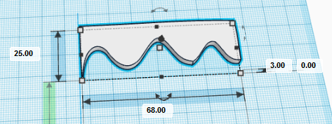
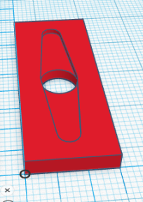
La forma generada debería tener el siguiente aspecto (ajustad el tamaño a 68x25x3 mm, se ha ampliada la anchura con respecto a su valor nominal para eliminar posibles «sobrantes» en los bordes del pie):
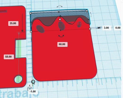
Ahora podemos posicionar la forma generada justo en la parte superior del pie, en la coordenada (-1,58,0) mm y darle un aspecto hueco para generar la forma de los dedos de los pies.
Para las uñas de los pies, simplemente debemos crear elipses a partir de cilindros girados convenientemente posicionados y con el tamaño que consideremos más conveniente.
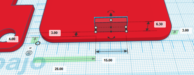
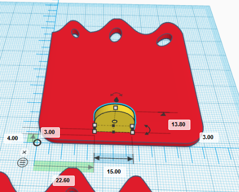
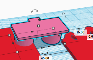
Para generar el tobillo, crearemos un cubo de dimensiones (15,3,6.3) mm y lo posicionamos en la coordenada (28,4,3) mm.
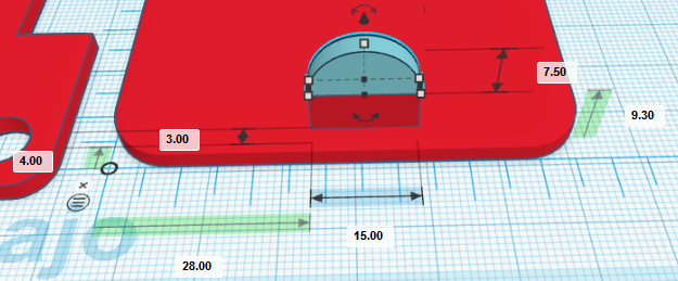
Luego creamos un techo curvo de dimensiones (15,3,7.5) mm, posicionado en la coordenada (28,4,9.3) mm.
Finalmente crearemos un agujero pasante para el remache. El diámetro del remache es de 2mm, con lo que el cilindro debe ser de dimensiones (2,2,3) mm y debemos girarlo con respecto al eje X.
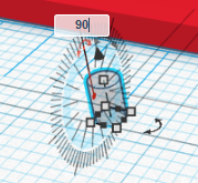
Posicionamos el cilindro en la coordenada (34.5,4,9.3) mm
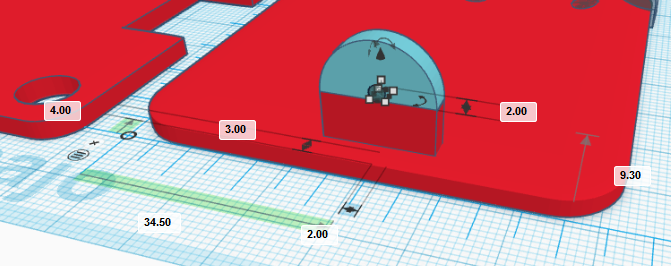
Para generar la pieza que conforma el pie, sólo debemos agrupar todas las geometrías creadas
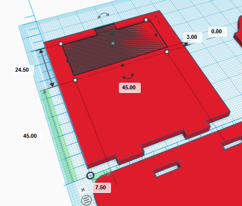
Para el diseño del pie derecho, debemos copiar el pie izquierdo y pegarlo (ahora pie derecho) en la esquina superior derecha del plano de trabajo y desplazamos la regla y nos aseguramos que el pie derecho está posicionado en la coordenada (0,0,0) con respecto a la regla.
Ahora debemos desagrupar las geometrías y reagruparlas de forma que la planta del pie, junto con la geometría de los dedos de los pies y las uñas forman una única geometría agrupada, mientras que las geometrías correspondientes al tobillo, formarán otra geometría agrupada independiente. Se ha asignado un color diferente a cada una de las dos nuevas geometrías agrupadas
Ahora debemos de girar 180º con respecto al eje Y (dar la vuelta a la pieza de la planta del pie) y desplazar la pieza del tobillo, cuyas nuevas coordenadas deben ser (22.6,4,3) mm.
Finalmente, agrupamos las dos geometrías para conformar el pie derecho
Diseño de las piernas
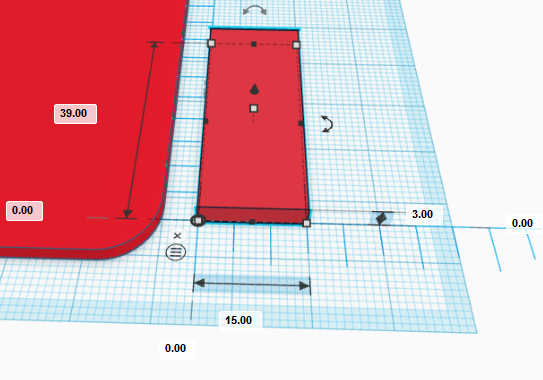
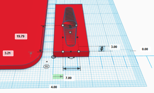
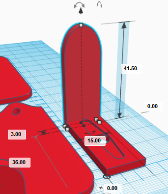
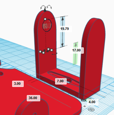
El diseño de las piernas del robot es el mismo para ambas piernas. Describiremos el proceso de creación de la pierna (izquierda) que empezaremos por recolocar la regla justo a la derecha del pie izquierdo y creando un cubo de dimensiones (15,39,3) mm posicionado en la coordenada (0,0,0) con respecto a la regla.
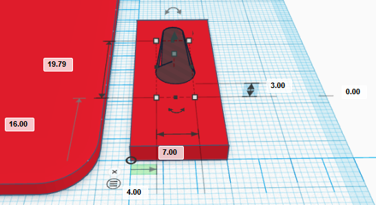
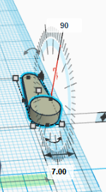
Ahora importamos el fichero «servo_horn.stl» (disponible en los ficheros de los componentes del robot justo al principio). Hacemos que la forma sea hueca, de damos la vuelta 180º y la posicionamos en la coordenada (4,16,0) mm.
Repetimos el procedimiento otra vez, pero ahora la manilla del servo debe apuntar hacia abajo, con lo que debemos también girarla 180º con respecto a la ya existente y posicionarlo en la coordenada (4,3.21,0) mm.
Si agrupamos los objetos, deberíamos obtener el siguiente resultado:
Ahora crearemos la parte delantera de la pierna. Para ello creamos un cubo de dimensiones (15,3,30) mm y lo posicionamos en la coordenada (0,36,0) mm.
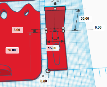
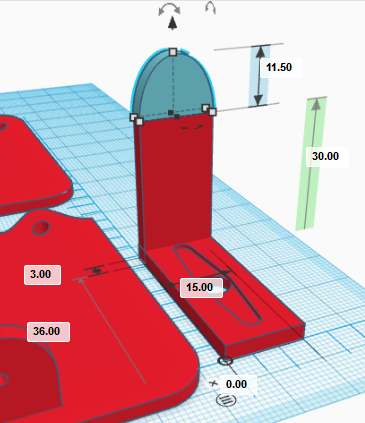
Para darle una forma redondeada a la parte delantera de la pierna crearemos un techo curvo con dimensiones (15,3,11.5) mm y lo posicionamos en la coordenada (0,36,30) mm.
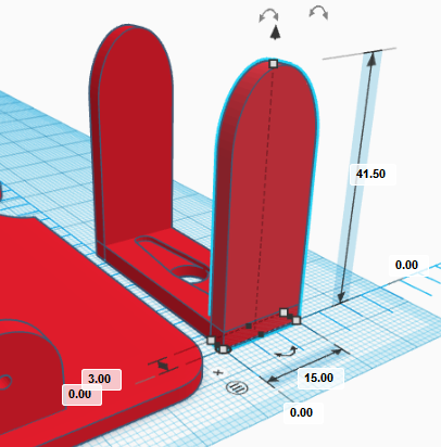
Agrupamos las piezas de la parte delantera
y copiamos y pegamos la pieza para crear la parte trasera de la pierna. La nueva pieza la posicionamos en la coordenada (0,0,0) mm.
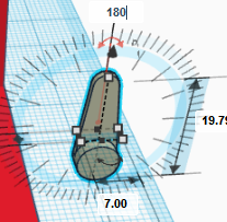
Ahora importarmos la manilla del servo «servo_horn.stl» y la rotamos 90º en X, y 180º en Y según se muestra en la siguiente secuencia de operaciones hasta lograr la orientación mostrada
Una vez tenemos la manilla del servo orientada correctamente, la posicionamos en la coordenada (4,36,17) mm y hacemos que sea hueca.
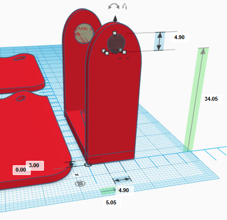
Para el orificio del cojinete crearemos un cilindro hueco girado 90º con respecto al eje X y de dimensiones (4.9,3,4.9) mm (una vez girado). Lo posicionamos en la coordenada (5.05,0,34.05) mm
Para finalizar la pierna, agrupamos todos los objetos
Tal y como ya se ha comentado, la otra pierna es idéntica, con lo que copiamos y pegamos la pieza creada y la posicionamos convenientemente.
Diseño de la cara
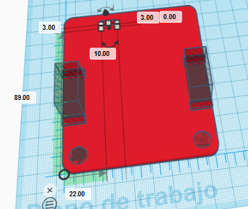
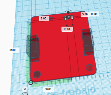
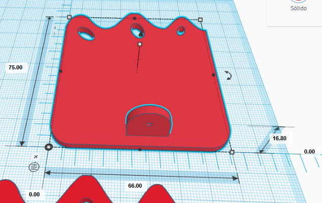
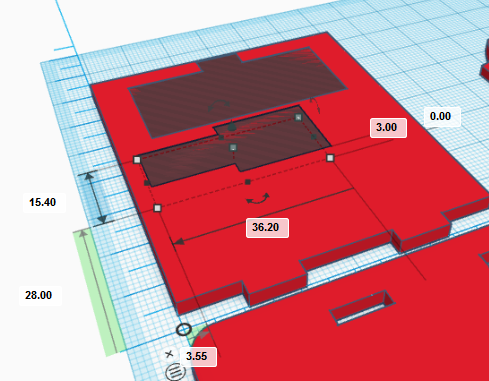
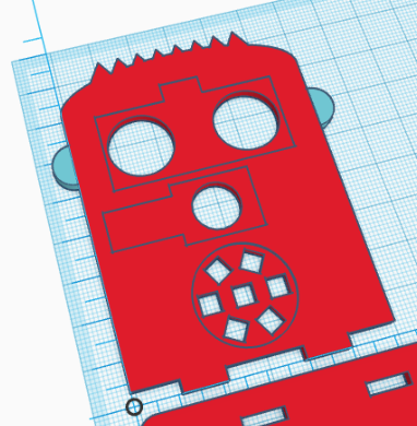
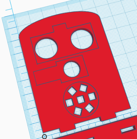
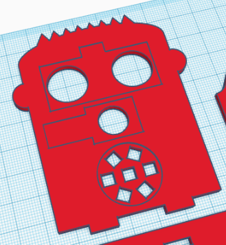
Para el diseño de la cara desplazaremos la regla para diseñar la pieza en la esquina superior izquierda. Creamos un cubo de dimensiones (60,70,3) mm y lo posicionamos en la coordenada (0,0,0) mm.
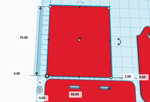
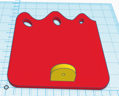
Ahora creamos tres cubos huecos de dimensiones (11,3,3), (18,3,3) y (11,3,3) mm posicionados en las coordenadas (0,0,0), (21,0,0), y (49,0,0) mm, respectivamente. Agrupamos los objetos de la cara para crear la geometría mostrada
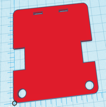
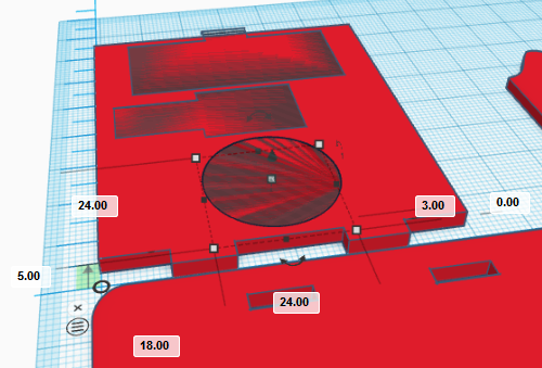
Ahora importamos el fichero «HC-SR04.stl» y lo giramos 180º con respecto al eje X, tal y como se muestra.
Hacemos el objeto hueco y lo posicionamos en la coordenada (7.5,45,3) mm.
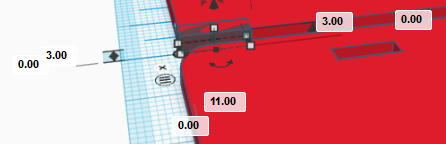
Repetimos este procedimiento de forma similar con le fichero del zumbador «», es decir, lo giramos 180º con respecto al eje X y lo hacemos hueco y lo posicionamos en la coordenada (3.55,28,3) mm.
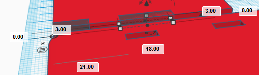
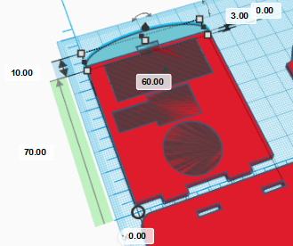
Para la boca importarmos el fichero «LED_round_strip_ws8212.stl» y repetimos el procedimiento de girar 180º con respecto al eje X, hacerlo hueco y lo posicionamos en la coordenada (18,5,3) mm.
Para decorar la cara del robot, podemos hacer un pelo siguiendo un procedimiento similar al que se ha hecho con los dedos de los pies o sencillamente hacer que la cabeza sea redondeada, por ejemplo incorporando un techo curvo tal y como se muestra.
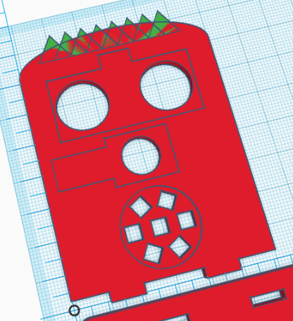
Aquí mostramos algunas ideas…
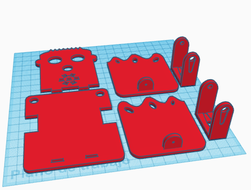
Con las piezas creadas, estamos en disposición de imprimir las piezas.
 [:en]In this entry, we describe the process to design in TinkerCAD the robot DYOR bPED.
The expected result after finishing these steps is shown below:
First, we will download some necessary STL files to create holes for our components:
Base Design
We will start by adding the ruler to our workplane. Put it somewhere close to the left-bottom corner of the workplane. After that, we need to create a cube with dimensions (82,97,3) mm and place it at the coordinate (0,0,0) mm with respect to the ruler. We also need to change the «radius» property to 1.22 mm to create rounded corners.
Import the file «Servo.stl» and place it at coordinate (0,25.7,-13) mm, turn it 180º so that the axis points downwards and select the hole shape.
Now, we will repeat this procedure with the other servo by placing it at the coordinate (70.2,25.7,-8) mm, also with the servo axis pointing downwards and hole shape.
Now, we will create a cylinder of dimensions (9,9,3) mm and place it in the coordinate (3.5,3.5,0) mm. The shape will be a hole so that servo cables can pass through it.
In the same way, we will create another cylinder with the same dimensions and place it in the coordinate (69.5,3.5,0) mm so that cables from the other leg can pass through too.
Now, we will create the holes to fit the robot’s front part. They are two cubes with dimensions (10,3,3) mm placed at coordinates (22,89,0) mm and (50,89,0) mm, respectively.
Finally, we will group all shapes to generate the part to print.
Feet Design
Now, we will move the ruler to the right, where we will start creating a robot foot. If necessary, you can move the already created base part to the left to leave more space. In order to design the left foot, we will create a cube with dimensions (66,75,3) mm placed at coordinate (0,0,0) mm with a rounding radius of 2.44.
In order to generate the feet, we will use an advanced feature of TinkerCAD in combination with Inkscape. The aim is to create a shape that we will use to remove part of the cube we have created so that we have three toes.
First, we need to draw, in Inkscape, a Bézier curve with an approximate size of 66×25 mm (make sure you are using mm):
This is the file we have used:
After that, we need to create our own shape in TinkerCAD based on extrusion (which means that from a 2D shape, we will create a 3D shape by providing a proper height). Please, follow the instructions as given:
Once we are in the Shape Generator tool, by default it will be shown a circle. In the left side menu, we can manage our «resources» by accessing the «resources» tab. We must delete the default geometry and import our file «toes.svg» with toes shape.
For some unknown reason, TinkerCAD does not recognize the proper units by default. For that reason, we need to change the recently imported file (on the left menu within the «resources» tab) and replace width=»66mm» and height=»25mm» with width=»66px» and height=»25px», respectively.
Now, in the «main.js» file, we can assign the geometry we have just imported by replacing the name ‘circle-2RL4RC.svg’ with ‘toes.svg’ inside the function «shapeGeneratorDefaults» and the line «var height = 20.0;» with «var height = 3.0;» within the «process» function. Save the changes to take effect.
After all this process, we should have the following shape (we have fit the size to 68x25x3 mm, slightly larger than the original shape so that we make sure that the borders are completely removed):
Now, we can place the new shape just in front of the foot, at coordinate (-1,58,0) mm and convert it to a hole shape. We can also create three cylinders of height 3mm with an arbitrary shape as if they were nails of the toes with arbitrary orientation.
In order to create the ankle, we will create a cube of dimensions (15,3,6.3) mm and place it in the coordinate (28,4,3) mm.
Then, we will create a round roof with dimensions (15,3,7.5) mm, place it in the coordinate (28,4,9.3) mm.
Finally, we will need to create a hole for the rivet. The diameter is 2mm so that the dimensions of the cylinder will be (2,2,3) mm and we will need to rotate it with respect to X-axis 90º degrees.
Place the cylinder at coordinate (34.5,4,9.3) mm
Now, group all foot-related shapes and we’ve got it!
To create the right foot, we will copy the left foot and place it on top-right corner of the workplane. We will move the ruler and make sure the foot is placed at coordinate (0,0,0) mm with respect to the new position of the ruler.
Now, we need to ungroup the geometries corresponding to the right foot and regroup them so that the objects corresponding to the foot sole and toes are all grouped together and the ankle (with the hole) is another group. We have assigned two different colours to each group.
Now, we need to rotate 180º with respect to the Y-axis (mirror it) and move the ankle to the new coordinates (22.6,4,3) mm.
Finally, we will group the objects together so we have the right foot.
Legs Design
The design for the legs is the same for both legs. We will describe the design process for one of them (let’s say left leg). We need to move the rule to the right of the left foot and create a cube with dimensions (15,39,3) mm placed at coordinate (0,0,0) mm with respect to the ruler.
Now, we can import the STL file «servo_horn.stl» and make it hole shaped. Rotate it 180º and placed it at coordinate (4,16,0) mm, as shown.
Repeat the process again, but now, the horn will be pointing downwards, which means that we need to rotate it 180º with respect to the existing one and place it at coordinate (4,3.21,0) mm.
If we group objects, we should have the following result:
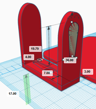
Now, let’s create the front side of the leg. So we need to create a cube of dimensions (15,3,30) mm and place it at coordinate (0,36,0) mm.
In order to have a rounded shape, we need to create a curved roof with dimensions (15,3,11.5) mm and position (0,36,30) mm.
Group the parts corresponding to the front-side leg
and copy and paste it to create the rear-side part and place it at coordinate (0,0,0) mm.
Now, we import again the STL file «servo_horn.stl» and rotate it 90º with respect to X-axis, and 180º with respect to Y-axis as shown in next figures:
Once rotated, we can place it at coordinate (4,36,17) mm and make it hole.
In order to create the hole for the ball bearing, we need to create a cylinder rotated 90º with respect to the X-axis and dimensions (4.9,3,4.9) mm (once rotated). Place it at coordinate (5.05,0,34.05) mm
In order to complete the leg, we will simply group all objects
As mentioned before, the right leg is the same so we just simply need to copy and paste it at a different position (to the right of the right foot).
Face Design
To create the robot’s face, we will move the ruler to the top-left corner of the workplane. We start by creating a cue of dimensions (60,70,3) mm and positioning it at coordinate (0,0,0) mm.
Now, we will create three hole cubes with dimensions (11,3,3), (18,3,3) and (11,3,3) mm placed at coordinates (0,0,0), (21,0,0), y (49,0,0) mm, respectively. Group them to create the geometry shown:
Now, we need to import the file «HC-SR04.stl» and rotate it 180º with respect to the X-axis as shown.
Make the object hole and place it at coordinate (7.5,45,3) mm.
Repeat this process with the buzzer file, rotate it 180º with respect to the X-axis, make it hole and place it at (3.55,28,3) mm.
For the LEDs strip (robot’s mouth), we will need to import the file «LED_round_strip_ws8212.stl» and repeat the process of rotating the object 180º with respect to the X-axis, make it hole and place it at coordinate (18,5,3) mm.
In order to add some fancy decorations, we can create some hair, following a similar process used to create the toes or simple que can make the front face rounded as shown.
Here we also show some ideas…
With all parts created, now you are in position of 3D Printing them.
[:]