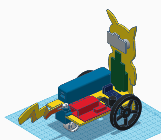
In this entry, we show the assembly of DYOR PikaBot with TinkerCAD and make with laser cutting
Components:
- Arduino Nano + Shield Arduino Nano I/O (red)
- Powerbank (blue)
- Ultrasound HC-SR04 (grey)
- Buzzer (black)
- Servos SG90 (blue) in the frontal face
- Servos FS90R (blue) in the base
- Bluetooth (dark blue)
- Linetracker TCRT5000 (dark blue)
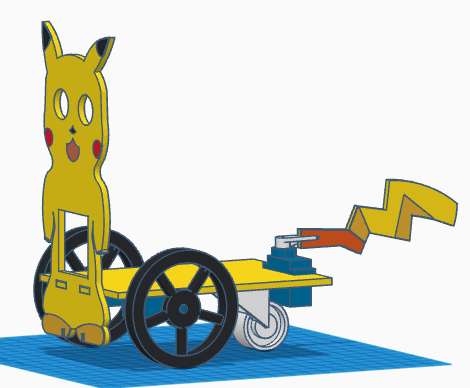
- Caster wheel (white)
- FS90R wheels (black)
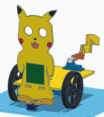
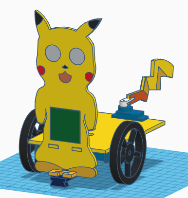
- LED Matrix (green)
Instructions:
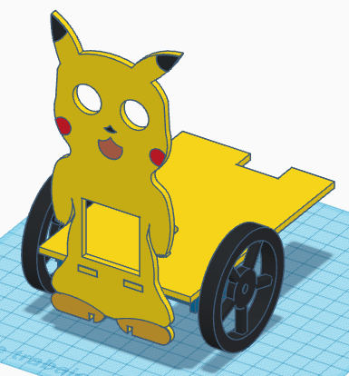
Glue both parts, the base and the frontal face.

Glue the FS90R servos to the base, the servo axis has to be as far as possible to the frontal face and screw the wheels to the servos.
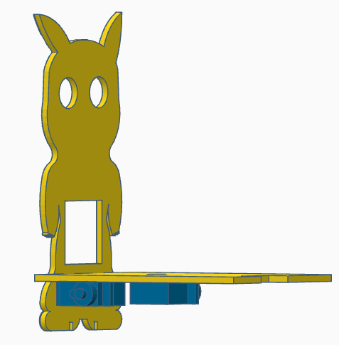
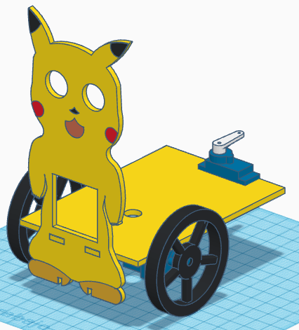
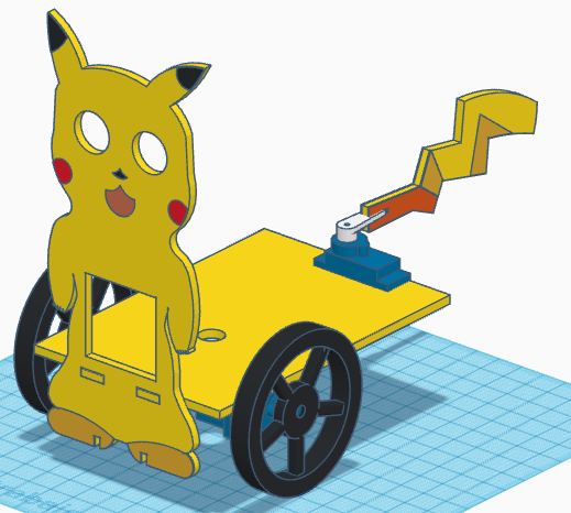
Now, clue the SG90 position servo at the rear so that the axis is centred with respect to the base. The servo horn must be screwed to the servo axis so that the servo at its middle position is just pointing as shown in the figure. Glue the tail to the servo horn.
Glue the caster wheel to the base
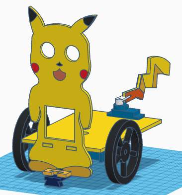
Glue the TCRT5000 support just below at the feet and glue the TCRT5000 sensor to the support (glue it so the sensor is below the feet horizontally).
FS90R and SG90 servos cables and TCRT5000 cables can be now pass through the base hole. After that, we can glue the LEDs matrix to the frontal face (cables pointing upwards).
Glue the ultrasonic sensor HC-SR04
Finally, glue the Arduino electronics, Powerbank, buzzer and Bluetooth module to the robot base.