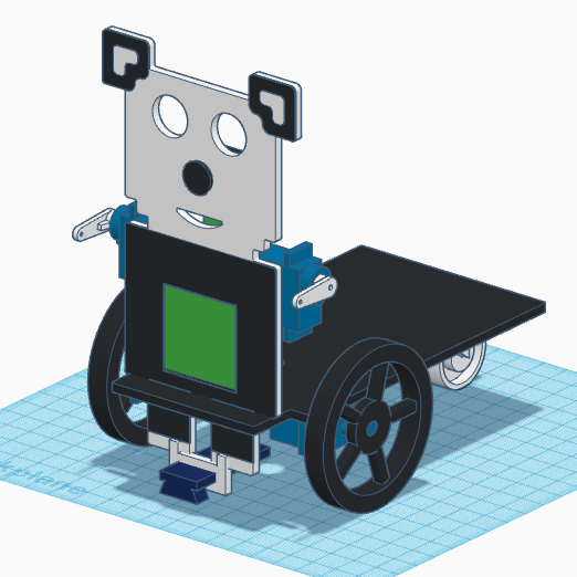
[:es]En esta entrada os mostramos el ensamblaje del robot DYOR PandaBot realizado con TinkerCAD y fabricado con corte láser.
Componentes:
- Arduino Nano + Shield Arduino Nano I/O (rojo)
- Powerbank (morado)
- Ultrasonido HC-SR04 (gris claro)
- Zumbador de sonido (negro)
- Servos SG90 (azul) en el frontal
- Servos FS90R (azul) en la base
- Bluetooth (gris claro)
- Seguilíneas TCRT5000 (azul oscuro)
- Rueda loca (blanco)
- Ruedas FS90R (negro)
- Matriz de LEDs (verde)
Instrucciones:
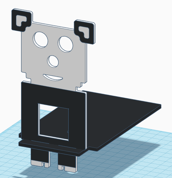
Colocar la pieza del frontal junto con la base y pegarlas.
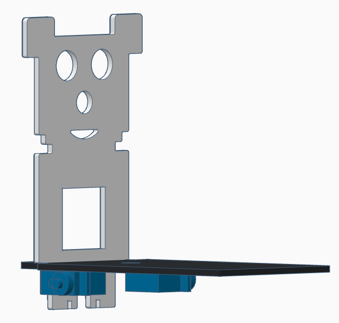
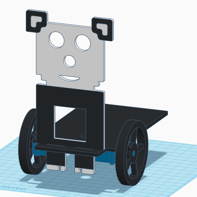
Pegar los servos FS90R a la base, estando el eje lo más atrás posible y atornillar las ruedas.
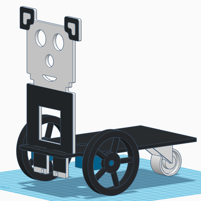
Pegar la rueda loca en la parte trasera de la base.
Pegar el soporte del sensor TCRT5000 en los pies y pegar el sensor al soporte (por dentro).
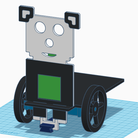
Pasar los cables, tanto de los servos FS90R como del sensor TCRT5000 por el orificio que tiene la base. Una vez pasados los cables, podremos pegar la matriz de LEDs al frontal con el conector de entrada apuntando hacia arriba.
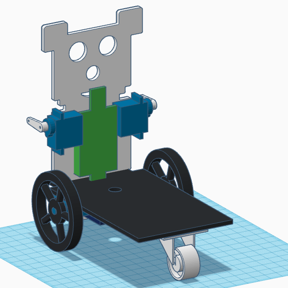
Pegar los servos SG90 en la parte trasera del frontal y atornillar la manivela (debemos asegurarnos que la posición de la manivela que se muestra es la de la posición intermedia de 90º).
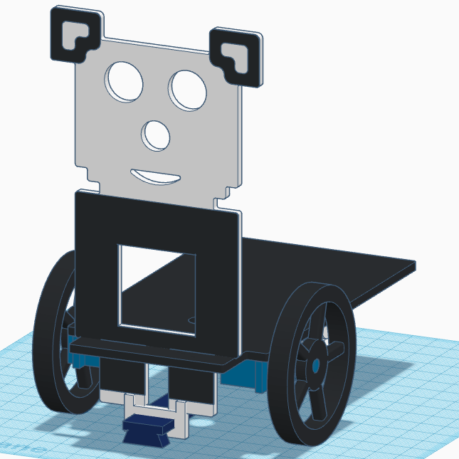
Colocar los cables de la matrix de LEDs en el conector que queda en la parte superior y después pegar el zumbador de sonido.
Pegar el ultrasonido HC-SR04 con los cables apuntando hacia arriba.
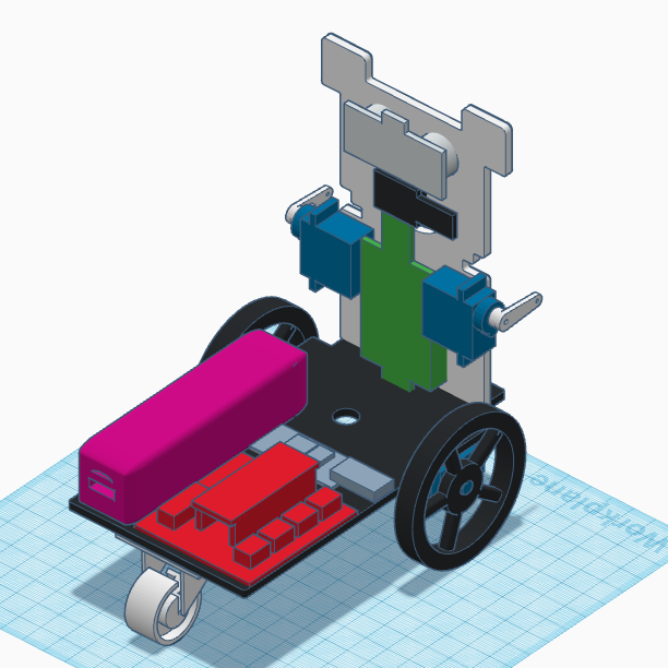
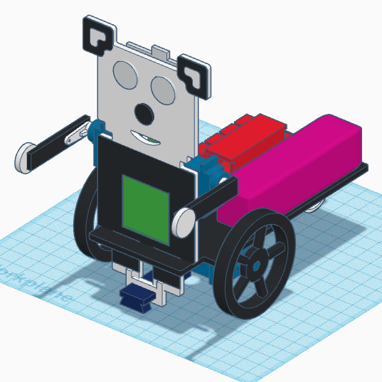
Pegar el powerbank, placa de Arduino (Shield+Arduino Nano) y bluetooth en la base del robot y colocar los cables correspondientes.
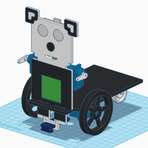
Finalmente pegar los brazos a las manillas de los servos SG90 y las manos redondas (orificios del ultrasonido) a los brazos.
 [:en]In this entry, we show the assembly of DYOR PandaBot with TinkerCAD and make with laser cutting.
Components:
- Arduino Nano + Shield Arduino Nano I/O (red)
- Powerbank (magenta)
- Ultrasound HC-SR04 (light grey)
- Buzzer (black)
- Servos SG90 (blue) in the frontal face
- Servos FS90R (blue) in the base
- Bluetooth (light grey)
- Linetracker TCRT5000 (dark blue)
- Caster wheel (white)
- FS90R wheels (black)
- LED Matrix (green)
Instructions:
Glue both parts, the base and the frontal face.
Glue the FS90R servos to the base, the servo axis has to be as far as possible to the frontal face and screw the wheels to the servos.
Glue the caster wheel to the base.
Glue the TCRT5000 support at the feet and glue the TCRT5000 sensor to the support (glue it so the sensor is inside the support).
FS90R servo cables and TCRT5000 cables can be now pass through the base hole. After that, we can glue the LEDs matrix to the frontal face with the input connector pointing upwards.
Connect the cables of the LEDs matrix to the top connector and glue to SG90 servos to the back of the frontal face and screw the horn to the servos (we should have previously check that the servos are an intermediate angle of 90º), as shown.
Now, glue the buzzer.
Glue the ultrasound sensor to the corresponding holes in the frontal face so that connectors pins are pointing up.
Glue the Powerbank, Arduino Shield+Arduino Nano and Bluetooth to the robot’s base and connect the corresponding cables.
Finally, glue the arms to the servo horns and glue the rounded hands.
[:]