This post describes the DecaTruck-bot
Components
- 1 x Arduino UNO + shield sensor 5.0
- 1 x Bread bord mini 170 pin
- 1 x Ultrasonic sensor
- 1 x HC-05 Bluetooth module
- 1 x 5V Buzzer
- 1 x Motor driver L298N
- 1 x Led matrix 8×8
- 1 x MG90S servomotor
- 2 x tcrt5000 sensor
- 2 x DC motors + wheels
- 1 x 2WD car chassis
- 4 x AA alkaline battery 1.5 V
- 1 x 9 V battery
- 1 x grip
- Jumper cables F-F, M-F
DESCRIPTION
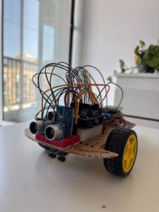
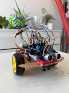
To assemble the robot, we first had to take the robot base and mount the two DC motors at the ends and then add the two tyre wheels and fix the battery compartment for the 4 AA 1.5 V batteries placed in series to have a total voltage of 6V) underneath the robot (to save space).
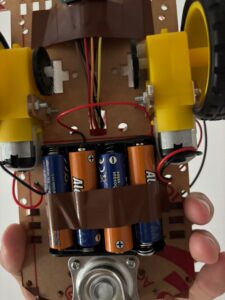
These batteries will only be used to power the L298N motor driver and the two DC motors.
Two cables must be soldered to the motors, which will be inserted into the appropriate spaces (OUT1, OUT2, OUT3, OUT4) of the L298N motor driver in order to be properly powered.
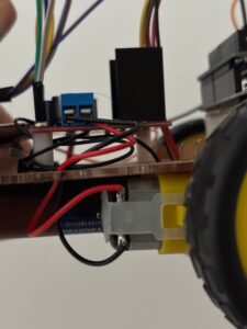
In the section labelled VCC we insert, by convention, the red cable from the battery compartment, while in the section next to it labelled GND we insert the black cable from the battery compartment together with another cable that will connect to the GND of the arduino shield so that there is a common GND between the two components.
To finish with the motor driver it is necessary to connect 6 jumper cables F-F to the present pins ENA, IN1, IN2, IN3, IN4, ENB which will be used to control the DC motors.
Switching to the arduino, jumper cables from the driver can be connected to 6 digital pins, leaving aside pins 0 and 1, which are exclusively dedicated to receiving and transmitting commands via the bluetooh module.
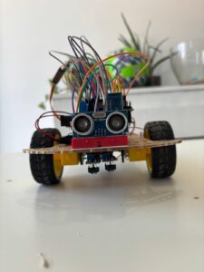
At the front end of the robot glue the mini bread board, which will be the holder for the ultrasonic sensor, the HC-05 module and the buzzer.
In order to use these 3 components, 5 digital pins are needed, in addition to the normal VCC and GND.
Since they draw little current overall, it is possible to connect the power supply directly to the VCC pins of the shield.
As mentioned earlier, pins 0 and 1 are dedicated to the Bluetooth module and to connect it correctly, the HC-05’s TX pin must be connected to pin 0 which is used to receive data (RX) while the module’s RX pin to pin 1 to transmit it (TX).
It is important to bear in mind that, when loading code, you need to disconnect pins 0 and 1 to avoid conflicts with the serial port.
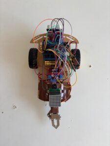
Next, the MG90S servomotor must be connected, which will be used to open and close the clamp to move objects, and the LED matrix, which will be used to display images on it.
Since these two components draw more current, it is preferable not to connect the power supply pins directly to the VCC pins of the shield, but to use the breadbord to power them.
To do this, simply use an M-F jumper cable from a VCC pin on the shield to any 5-pin line on the breadbord and then connect the power cables for the servomotor and the LED matrix to the same line.
Due to the number of components we used, it is not possible to connect them all to the digital pins as there are only 14 of them.
For this reason, an analogue pin will be used as digital.
The analogue pins are those required to use the two tcrt5000 sensors located underneath the robot.
Finally, we can power the arduino with the 9 V battery and by doing so, the whole robot is fully connected and ready to be configured and controlled via Bluetooth.
CONTROL
For control via Bluetooth, a python script is used that simulates a controller where it is possible to connect to the arduino, make it move and allow it to perform certain functions, even autonomously.
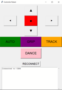
First, if the connection with the HC-05 is not made automatically, press the RECONNECT button to start the Bluetooth connection.
From the proposed image it can be seen that there are the classic directional arrows and a stop button that are used to move the robot in all directions.
To use these keys, it is not necessary to press them with the mouse, but simply by pressing:
- “w’ to move forward
- “s” to go backwards
- “a” to rotate left
- “d” to rotate right
Holding down the relevant button causes the robot to move, while releasing the pressure will automatically press the ‘x’ button and the robot will stop.
During movement, the LED matrix will display arrows to indicate where the robot is moving and an X if the robot is stationary.
Four buttons with different functionalities are visible in the image.
AUTO
This command is activated by pressing the ‘q’ button once.
In this mode, the robot runs straight ahead until the ultrasonic sensor detects an obstacle in front of it.
Once detected, the robot will autonomously turn 90 degrees to the right.
GRIP
By pressing the ‘r’ button, the robot opens and closes the gripper, allowing you to grab objects and move them wherever you want.
TRACK
This button allows you to enter line tracking mode by pressing ‘e’.
In this mode, the robot will use the two tcrt5000 sensors to follow a path consisting of black insulation tape, in order to have a high colour contrast with the surface being used (table or floor).
The operation of line tracking is very simple and depends on the values read by the sensors. Taking a white surface in contrast to a black tape as an example, the average values recorded by the sensors are:
- 60 for the white surface
- 600 for black tape
By observing these values, it is possible to establish a trashold (e.g. 300) that divides white (<300) from black (>300).
Based on the left (left) and right (right) sensor readings, we have four possibilities:
- SX detects black and DX detects black then the robot is on the path and moves forward
- SX detects black and DX detects white then the robot turns left to return to the path
- SX detects white and DX detects black then the robot turns right
- SX detects white and DX detects white then the robot has gone completely off course and for this reason automatically turns back and continues with line tracking.
Furthermore, should the ultrasonic sensor detect an obstacle on the path, the robot will turn 180 degrees and continue its movement in the opposite direction.
DANCE
This mode is activated with the ‘f’ button.
As can be guessed from the name, pressing this button will cause the robot to perform a dance.
The tune of Super Mario Bros. is played through the buzzer and once it is finished, the robot will perform a dance by turning on itself 360 degrees, first to the right and then to the left, and concluding by opening and closing the gripper in time to the music twice.
This dance is accompanied by the display of a smile on the LED matrix.