In this post I will explain DarthBot, the robot I have made for the mobile robotics subject at UPV. The robot is based on Dart Vader.
Desing
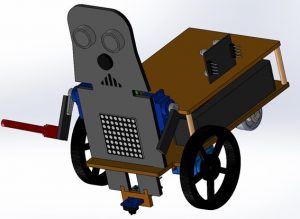
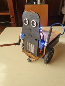
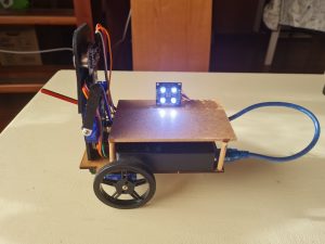
For the design, I have used a premade kit and I have modified it a bit adding a wood structure so that the wires and components are covered. The design made in SolidWorks and the real robot can be seen in these images:
Components
The materials used are the ones included in the kit.
- Arduino Nano
- I/O Extension Shield for Arduino Nano
- Powerbank 3600 mAh USB
- Mini USB wire
- 2 FS90R servos (wheels)
- 2 wheels for FS90R
- 2 SG90 servos (arms)
- Caster wheel
- HC – SR04 ultrasound sensor
- KY – 006 Buzzer
- LED matrix
- TCRT500 (line follower)
- SPP- C Bluetooth
- 3 mm wood base
- 3mm wood frontal panel (Darth Vader)
For the wood structured I have used a 4mm diameter wood stick, cut it in four equally long pieces and use it to secure the 3 mm wood panel that covers the electronics of the robot.
Features
The main code of the robot is designed with Facilino, but I have made some little changes in the Arduino code, so the robot works better.
The robot has 4 different features:
- Remote control. You can control the robot movements using the app in your phone.
- Line follower. The robot will follow a path marked with a black tape in a white background.
- Colour recognition. Depending on the colour the robot detects, it will stay on standby or move its arms to attack it. The colours it can detect are blue, red, and green. It will stay put and show the Death Star in the LED matrix if it detects red. If the colour detected is blue or green, it will attack moving its arms while the LED matrix shows a lightsaber. While it’s in this mode, it will play the Imperial March.
- Keep distance. With the ultrasound sensor, it will detect the object that is in front of it; if it’s far away it will follow it and if it’s too close the robot will go backwards. If it is in the middle ground, the robot will not move.
Mobile App
The mobile app used to control the robot has been designed with MIT AppInventor 2. You can see the app on the following image.
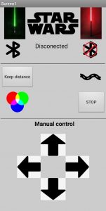
At the top of the screen, there are the buttons to connect the app to the robot via Bluetooth. In the centre it will be shown if it is connected or not.
In the middle of the screen, you can see de buttons for the different features of the robot. The button on the top left starts the keep distance mode. The button on the top right initiates the line tracking mode, down left there is the button for colour recognition mode. Down right, there is the last button which stops the other three modes.
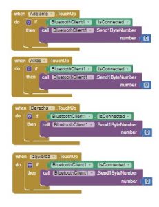
At the bottom of the screen, it is shown the remote control of the robot. With these buttons you can control the robot’s movements manually.
When you push one of these buttons, the app will send a byte number to the robot through Bluetooth. When you click on de Stop button or you push up one of the remote control buttons, the app will send a 0, meaning that the robot has to stop what it’s doing. The code of the app can be seen in these images.
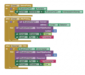
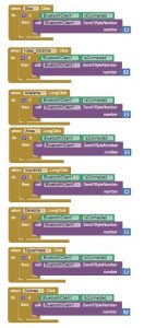
So, the robot will receive this number and will execute one of the features. For example, if we send 1 it will enter the keep distance mode, or if we send 6 it will start the line following mode.
For the remote control, while we keep pushed the button, the robot will move, but if you stop pushing the button, the app will send 0 and the movement will stop.
Video
Author
Daniel Moreno