In this blog post, the assembly and design of the ImperialBot will be explained.
Design and Components:
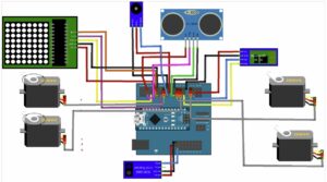
- Wheels and Motors: Two steerable wheels, two Micro servo SG90, two Micro servo FS90R and a caster wheel.
- Sensors: Ultrasonic Sensor HC-SR04 and an IR line following module (TCRT5000).
- Base and Power: Aluminium plate and a 9V battery.
- Electronics: Arduino Nano (v 3.0) with an adapter (I/O extension shield), motor driver (DRV 8833), Bluetooth module, connection cables, Buzzer KY-006.
Electrical Build:
Functions
- Line Following
For the programming of ImperialBot facilino programm was used to generate Arduino code. For the line following, values for should be defined for black and white for the line. To determine the constants for black an white, I wrote a code in Arduino, which you can find below.
const int sensorPin = A0; // The analog pin connected to the line sensor
void setup() {
Serial.begin(9600); // Initialize serial communication
Serial.println(“Setup complete”); // Debugging message to indicate setup completion
pinMode(sensorPin, INPUT);
}
void loop() {
int sensorValue = analogRead(sensorPin); // Read the sensor value
Serial.print(“Sensor Value: “);
Serial.println(sensorValue); // Print the sensor value to the Serial Monitor
delay(500); // Delay to read the values
}
With his code I put my robot on the track and determined that it gives the output of approximately 900 when I put my robot on the black line and a value between 30 and 200 (approximated as 100) when it is not on the line. These constants can change when the robot is on different tracks with other light conditions. But with the help of the given code it can be determined again.
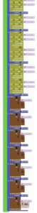
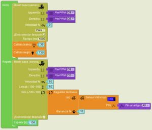
The following image shows the facilino code block for the line following.
In the following two videos, you can see the ImperialBOT (Darthy) performing line following on two different tracks.
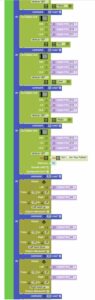
2. Obstacle Avoidance
In this second task if there are no obstacles recognized, a happy face is projected on the LED-Matrix and the robot moves freely. If there is an object detected, the LED-Matrix switches to an unhappy face and turns towards left.
3. Bluetooth Connection
To control the robot with Bluetooth MIT App Inventor was created. Below you can see the screenshot from the mobile device.
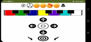
With the app, the robot can be moved left&right, forward&back, and also stop; the arms can be moved seperately and also at the same time. By clicking the piano board sounds can be creayed: do-re-mi-fa-sol-la-imperial march… And from the buttons on the top emtions can be selected: happy, sad, in love, angry. If the Darth Vader button is clicked, the famous quote of Darth Vader: “No…, I am your father!” is generated.With the bleutooth button on the top left, the robot can be connected and disconnected. When the accelerometer icon on the screen is pressed an hold, the robot can be controlled by tilting the phone. When the pressing is stopped, the robot goes back to being controlled by the buttons.
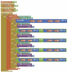
In MIT App Inventor, the moving of the robot by tilting the mobile devices is implemented with these blocks.
The first video shows the general functtions of the app and the second shows the accelerometer.
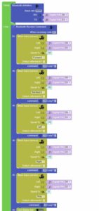
In the following, you can see the facilino code blocks for the Bluetooth function.