At the heart of our university project lies the transformation of a childhood toy – a remote control car – into a autonomous robot capable of navigating its environment using sensors and algorithms. We repurposed existing hardware.
Analyzing preexisting parts and RC car prework
Our first step was to thoroughly analyze the remote control car. We identified its electronic components and assessed the feasibility of integrating sensors for autonomous functionality. Understanding the behavior of the steering and throttle motors was crucial, as it laid the groundwork for our algorithm design. With the initial setup this was not yet possible. The car would also not operate with the remote. Initially our thought was that the speed controller wasn’t working correctly. The motor kept beeping after the electricity was turned on. This usually suggests that the motor is lacking any information and control input.
We ordered a new electronic speed control for the car and tested it again but with no success. The electrician at UPV proved to be very helpful and after spending quite a bit of time at the lab we could finally figure out that in fact a faulty battery was the problem, and the speed control was working fine. With a new battery the motor stopped beeping and as explained in the following chapter we could conduct some first tests.
The RC-car was built around 2005 by Tamiya, a manufacturer that still exists today and has a small but dedicated fanbase. All components are modular and rather standard so it should be a great base to start with for our robot. The car is the Tamyia Fighter with the DT02 base. The remote-control car is in a car like configuration with two motors, one for the steering axis in the front and one throttle motor in the back. The main motor is powered by a 7.2V NI-MH battery. The car is intended to be controlled remotely by a two-channel controller.
Since the robot base is quite a bit larger than the prebuild concepts and also has a larger turning radius we wanted to do something else than a line follower. Inspired by the maze solver from the Coppelia Sim lab sessions we are looking for a wall following algorithm.
Concept Development
With insights gained from our analysis, we conceptualized a plan. Our goal was to implement a wall-following algorithm, leveraging two Time of Flight (ToF) laser sensors on each side of the car to measure distances from surrounding walls. Additionally, an ultrasonic sensor mounted at the front would detect obstacles, ensuring the car could avoid frontal collisions. The two Time of Flight laser sensors (VL53L0X) on each side of the base should measure the distance to the sides of the walls. The front servo should then steer towards the closer wall and try to keep a predefined distance. Additionally, an ultrasonic sensor mounted at the front would detect obstacles, ensuring the car could avoid frontal collisions.
Procurement and Initial Testing
Upon finalizing our concept, we procured the necessary electronic components. As the components arrived, we focused on assembling and connecting them to the Arduino platform. Initial tests involved verifying the functionality of the throttle and steering motors through basic control code. Concurrently, we tested the sensors to ensure they reliably provided data necessary for autonomous operation.
Motor connection
The first tests were conducted with a simple code to test the functionality of the front steering servo and the back motor with its electronic speed control. Both worked very well and initial concerns regarding the minimal speed of the throttle motor being too high could be dismissed. The throttle motor is very powerful but with an angle setting of about 82 degrees a slow but consistent speed that will suit our task can be achieved. Thanks to the electronic speed control the back motor can be operated exactly like a servomotor.
With both motors being operational we could very easily connect them to the Arduino and after some first tests the controls seem to work fine. Previously we were able to test the basic functions of our motors with an Arduino Nano that unfortunately didn’t live long enough to encounter our sensors.
Arduino Sensor connection iterations
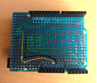
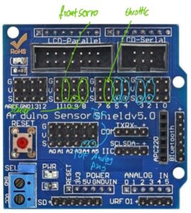
With the Arduino Uno and the help of a bread board we were able to connect the first ToF sensor to our board and finally get some sensor readings. To get a more final connection to the Uno and reduce the number of pins in the breadboard we tried to solder the necessary connections to a blank Uno expansion shield. We created a circuit plan for the ToF sensors and how they have to be connected.
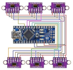
When using only a single sensor the connection is very straightforward. You can simply connect the pins for voltage and ground, the SDA to A4 and the SCL to A4. Using multiple VL53L0X sensors with a single Arduino can be achieved by giving each sensor a unique I2C address. By default, all VL53L0X sensors have the same I2C address (0x29), so we need to change the addresses after initializing each sensor. For the circuit all SDA and SCL pins need to be connected to the same analog pins.
Unfortunately, the soldering didn’t go as planned and we still couldn’t conduct proper tests for our ToF sensos. After working with a newly ordered presoldered expansion shield and a big breadboard we could test the function of all sensors, get the output readings.
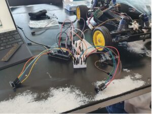
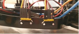
Even though we finally go a connection the whole setup was still very messy and as seen on the picture even with only two of our five sensor there a lot of cables used. Finally, we got our hands on a proper sensor shield with preinstalled pins for an even easier connection. This will be part of the final assembly.
Sensor mounting
To properly mount the sensor to our chassis our preferred method would have been to drill holes in the chassis of the char and use the M2 screw holes to tighten the sensors to the premarked positions. Due to a lack of equipment, we bought some cheap drills from the local chino market and, since they didn’t work, heated them over a candle to simply melt our holes in the chassis. This worked exceptionally well and with the help of some glue and nails for pins we secured our ToF sensors in the predetermined spots. The front sonar sensor is only responsible for a wall detection to the front and doesn’t have to be in precise location so it is glued to the front bumper.

Testing
After the base setup with sensors and connected motors and the first lines of code were in a working state we went to the testing phase. Our setup enabled us to gather real-time data in the Serial Monitor to understand the behavior of the code and the sensor data. Iterative coding and testing sessions allowed us to check and refine the algorithm, ensuring precise navigation and obstacle avoidance.
One of the most critical tools for bug fixing and testing was the serial monitor that provided us live information about the current actions that the robot was taking.
Difficulties with components
Using older components like the ones from our car comes with its own form of challenges. First of all, two Arduinos got damaged during our testing process and we are uncertain about the cause. Potentially the front servo that was being powered through the 5V connection on the board or the connected electronic speed control are responsible for the failures, but we are uncertain. The front servo itself proved to be quite problematic too.
Its behavior was generally very inconsistent and at times its only able to steer to the right or to left. When this happened, it could find a position close to the 90 degrees angle somewhat consistently. We rechecked the servo motor behavior with simple control code and found that the input angles were not being implemented correctly on the car. With the final setup and code we could achieve a full range of motion but the distances between left and right steering seem to be inconsistent.
Initially, only two of the ToF sensors worked. We checked for wiring issues, but the sensors also failed to work with the cable connections of the functioning sensors.
We concluded it was a soldering connection problem. After renewing the soldering connections, we received data from all five sensors: the four ToF sensors and the ultrasonic sensor at the front.
As long as we can set the neutral angle correctly this should only impact the behavior in the short term. The concrete steering angle values are most important for optimization.
Code
First, we wrote some code to test and understand the behavior of the steering motor and the throttle motor. Next, we wrote code to test the sensors, allowing us to monitor sensor data in the serial monitor and assess its reliability. We then combined the servo motor actuation for steering with the sensor data to observe the reaction time and establish a basis for the wall-following algorithm. After this worked, we included the throttle motor actuation in the code.
The two sensors on each side solution
The initial idea for our code was to work with a similar concept to the robot used in our lab session for the maze solver. We have two ToF sensors on each side which give two different ranges and can thus compute or recognize the current angle to the wall. For our code we planned on giving a range during which a wall is being followed and recognized, a range of distance during which the distance is acceptable and should be kept and a range where the distance to the wall should be increased. The plan was for the robot to get the actual wall distance through the average distance between the sensors. If the distance to the wall should be increased and the difference between the sensors is equal or within a predefined range, the robot would steer away from the wall for a bit before correcting the angle by trying to get the sensor to a more equal distance again. We tried to make this code work for a long time but in the end couldn’t make it work. Possible reasons include inconsistencies in the sensor data that interrupt the process without a filter, delays in the motor control, the distance between the sensors being too short and thus the difference in readings too minimal or mistakes in the codes logic.
Final code concept and explanation
Our final code will be explained and displayed here.
Initialization
In the setup function, the robot initializes its sensors and motors. Each ToF sensor is assigned a unique I2C address to allow individual readings. The HC-SR04 pins are set up for triggering and reading echo signals. The robot also sets up the servo motors for steering and throttle control. Initially, all ToF sensors are disabled to avoid conflicts during initialization, and then each sensor is enabled and initialized one by one. After setting up the sensors, the robot starts moving forward by default.
Loops
The main loop of the program reads sensor data and decides the robot’s state: searching for a wall, following a wall and stopping.
- Reading Sensor Data: The robot reads distance data from all sensors. If a reading fails, it is set to zero to ensure the robot does not act on invalid data.
- State Transitions: Based on the sensor data, the robot decides which state to transition to:
- SEARCH_WALL: The robot searches for walls on either side and transitions to —-FOLLOW_WALL if it finds one.
- FOLLOW_WALL: The robot adjusts its course to maintain a certain distance from the wall. It can turn left or right to stay parallel to the wall.
- STOP: If an obstacle is detected in front, the robot stops and waits before checking again. If there is still a wall or an obstacle in front, it drives backwards while steering to the right if there is a wall on the left and while steering to the left if there is a wall on the right.
The robot continuously prints sensor data to the serial monitor for debugging purposes. It also checks if there is a wall in front using the sonar sensor and if there are walls on either side using the ToF sensors. Depending on the detected distances, it adjusts its state and behavior accordingly.
Helper Functions
Several helper functions manage the robot’s movement and sensor initialization:
- moveForward(), moveBackward(): These functions control the throttle and steering to move the robot forward or backward. The moveForward() function sets the throttle for forward movement and straightens the steering. The moveBackward() function adjusts the throttle for reverse movement and steers the robot to the right.
- turnRight(), turnLeft(): These functions adjust the steering to turn the robot right or left while moving forward. The turnRight() function steers the robot to the right, and the turnLeft() function steers it to the left.
- stop(): This function stops the robot’s movement by setting the throttle to a neutral position.
- searchWall(): This function determines the direction to follow based on wall detection. If walls are detected on both sides, the robot decides which direction to follow based on the distances. If a wall is detected on one side only, it follows that wall. If no walls are detected, it continues to move forward while searching.
- followWall(): This function adjusts the robot’s course to follow the wall while maintaining a certain distance. If the robot is following a wall on the left, it adjusts its movement to keep a specified distance from the wall. If it is following a wall on the right, it does the same for the right side. If an obstacle is detected in front, it transitions to the STOP state.
Problem with the trace of the vehicle
One specific problem we faced was related to the placement of the ultrasonic sensor. Since the sensor is mounted in the middle of the car’s front, it doesn’t cover the entire width of the car. This limitation means that the sensor can miss obstacles that are in the path of the car’s wheels, leading to situations where the car gets stuck. In these instances, the sensor detects no obstacles, but the wheels hit an object outside the sensor’s detection range.
Here is a video demonstrating this issue:
Our final code is the following:
Final result
In the following video you can see the final result: