In this entry, we will show how to use some of the basic features of QCAD in order to create 2D designs which can be used for laser cutting.
Introduction
QCAD is a CAD (Computed Aided Design) software which includes a menu bar on top with an icon bar just below the menu bar. On the left there’s a toolbox and a set of property windows on the right. The console for introducing commands is just below an the design area is in the center of all.

Reference manual
This entry is not intended to be a complete reference manual for QCAD. The best place to get some information can be found in https://www.ribbonsoft.com/en/qcad-documentation with the latest features and also the reference manual.
Layers
Every CAD design is organized in layers. Layers allow us to organize information with different properties and they can be easily activated/deactivated. In the property window, there’s a window with the layers information. By default, QCAD always has the 0 layer, but we can add more. In particular, since this entry is oriented to serve as a basis for designing 2d drawings for laser cutting, we can use the standard template for laser cutting or create our own layers and assign a different color for each layer as shown:

Coordinate system
QCAD includes a 2D Cartesian coordinate system with absolute and relative values. All absolute values are referred to the drawing origin shon in the following image:
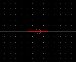
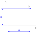
If we want to introduce an absolute coordinate in QCAD, we must indicate the X and Y coordinates separated with a colon “,”. They are usually written with the following notation in the console:
coordinate-x,coordinate-y
For instance, coordinate (40,30) is located 40 units to the right of the origin and 30 units above the origin.
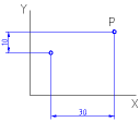
Cartesian coordinates can be also be referred to be relative to some specific point, different from the origin, which can be specified in the console with the following command:
@coordinate-x,coordinate-y
The point (40,30) relative to the point (10,20) can be expressed as @30,10.
Toolbox
Here we will explain some few commands which will help us to generate basic designs in QCAD. For lasser cutting it is highly recommended the use of polylines against line segments, arc segments, circles, ellipses, splines or any other curve, because the laser cutting machine can generally manufacture pieces much faster implemented with polylines than with the other curves. The reason it is very simple, polylines are indeed an ordered list of line segments and arc segments, which implies a contour which will also represent a continuous cutting (without “jumps” from one place to another). If two separate lines have a common point at their ends, they can be transformed into a polyline. In a similar case, if a line is contiguous to an arc segment, then both entities can be transformed into a polyline.
Therefore, it is very recommended that once the design is done, to transform all possible individual line segments or arc segments into polylines so that work time during cutting is reduced.
Most of icons that you will find in the toolbox, will be self-explanatory with the requested info at the console. For instance, when drawing an arc segment, there’s one icon related with creating it using three points. The console asks about introducing or selecting each of the points.
Basic commands:
Here you will find a set of basic commands such as redo, undo, copy, cut and paste. This is very intuitive so there’s no need for extra explanation.
Lines:
The most common type of lines are simple line segments, horizontal and vertical lines, rectangles or polygons:
line: draws a line with two points
lh,lv: draws a horizontal/vertical line
rectangle: draws a rectangle
polygon: draws a polygon with a center and a given number of sides
Arc segments and circles:
There are two main methods to create an arc segment and three different type of methods for creating a circle:
arc: Draws an arc segment from three points
arcc: Draws an arc segment with a point, centre and angle
circle: Draws a circle with a centre and one point.
circlecr: Draws a circle with a centre and radius.
circle3p: Draws a circle from three points
Polylines:
Polylines can combine line or arc segments. In order to change from a line segment to an arc segment, there’s a specific icon at the icon bar that will allow you to select the proper option.
![]()
Also, we can create a polyline form a selection of line and arc segments. In the toolbox, there’s an icon for “Create from segments”
![]()
that will allow you to select one entity and the ones (arc segments or line segments) which are continguous to each other will be removed and transformed into a polyline. Unfortunately, this is an advanced feature that it is only possible to use in the pro-version, which implies that the feature will be active for the first 15 minutes. In order to restart this timer, we can reboot our system, but in the end, there’s a limitation on the times the application is launch.
Modify menu:
The modify menu contains several tools that can be very useful if properly used. For instance, we can generate transformations such as rotation, translation, scaling and mirroring:

Another utility could be trimming, lengthen or shorten some entities. Trim implies that one entity will be trimmed (reduced) to the intersection point with another entity, while lengthen and shorten can extend or reduce the length of a given entity with a given amount (specified in the icon bar).

Another important utility, will be the “Divide” and “Break out”. With the divide tool, we can divide an entity at the specified point, in many cases with similar results as the trim command. The break out tool will introduce a small gap, let’s say 1mm, which can be specified in the icon bar, with the idea to break out an entity into two separate entities with a gap. The break out is very convinient in laser cutting when we want to have two parts which can be easily separated but kept joint for manufacturing purposes.
