Bearbot is a simple and very easy to build robot that can do more things than it seems at first glance. In this post you’ll see what bearBot can do and how it was build and programmed and also some useful tips that could help you do your own robot or take inspiration for other projects.
1. Materials
All the materials have been bought at the roboticafacil.es store and can be easily bought bundled. Here is what we need to build this robot:
- 3mm laser cut wood FDM (Arms)
- Arduino Nano v3.0
- I/O I/O Extension Shield for Arduino Nano
- USB mini cable
- PowerBank 3600mAh USB
- 2x Micro servo FS90R
- 2x Wheel FS90R
- 2x Micro servo SG90
- Caster wheel
- Ultrasound sensor HC-SR04
- Buzzer KY-006
- Led matrix 8×8 max7219
- Infrared sensor TCRT500
- SPP-C Bluetooth
- 20 Du-pont cables FF 20cm
- Facilino license
You can replace everything on this list with anything compatible, or you can just not buy something if you don’t want to use it in your project. The Facilino license however (although it is included for free) is very useful if you are not familiar with programming, or if you want some help with the basic code that interacts with the sensors/actuators.
Everything on the list worked as intended except the caster wheel, it was too rigid for the robot, so instead of rolling it just slided the wheel across the floor, it is not a serious problem but is something to keep in mind.
You will also need a way to assemble all the pieces, Bearbot has been glued together with a glue silicon gun, but you can use whatever method you prefer.
And finally you will need some device that can communicate with the SPP-C via Bluetooth, in this project an Android phone was used for this task.
2. Making sure everything works
The first thing you should do after receiving your electronics is trying them to see if they work. First we will try the arduino, to program it you will need to download the arduino IDE and copy the code that facilino generates, or write it yourself. Another option is to use the downloadable version of facilino, which integrates the arduino IDE software. Write a simple program that can read the USB serial and write the USB serial.
To connect the elements to the arduino you can just look the documentation on facilino, all you need to do is right click a block, press help and it will tell you how to connect the relevant electronic component, you can use this feature even without a license. Regardlees of that, it is really straghtforward and you just need to read what is written on the electronic and connect the cable to either voltage, ground or an analog/digital pin. The servo motors are a special case where you just have three cables and nothing more, you can just try to connect them both ways on the I/O shield, the correct connection is this, brown is ground, red is voltage and orange is the signal pin.
Once you connect an electronic activate/read it with the arduino and send the data through the serial. If everything works correctly you can proceed and start assembling the robot, if not you should ask a replace/refund, if you have bought the elctronics from roboticafacil or another serious shop you won’t have any problem, if you have bought them from aliexpress or similar it will be more difficult.
3. Building the robot
To build the robot you just need to assemble the pieces and glue them, it’s the easiest way. If the pieces dont fit you may need to sand the pieces, hopefully it wasn’t needed in this project. If you want to use the infrared sensor to follow lines on the floor you should glue/fix the legs of the bear around half a centimeter above the base, that way the sensor won’t be too close to the ground.
You should make sure that the servo motors and the caster wheel are well fixed using glue or screws, the rest of the electronics dont’t suffer strong forces so you can use less glue or just tape, that way you can remove them easily if you want to use them for another project or need to replace a broken electronic. In this case everything was glued with silicon, it is easy to use and can be done in around 30 minutes.
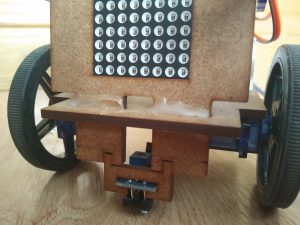
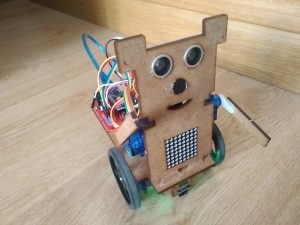
Here is how it looks.
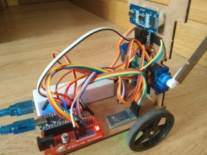
And these are details of the back and the wheels.
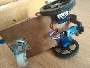
The electronics can be glued however you want, but it is important to try to glue the wheels correctly aligned and the caster wheel in the middle. In this project the caster wheel is not exactly in the middle and the robot moves good enough, but it could be better.
4. Programming the app
We will use an app to comunicate with the robot via bluetooth, this will allow us to send different commands easily and even allow us to send values to the robot to change variables at will. We used the MIT App inventor to program the app, this program is kind of limited but it is very easy to use, completely free and you can use it online without any download.
The app have only one screen with a lot of buttons and some sliders (is simpler that way), it also uses the bluetooth client, the accelerometer and two clocks. The button connect displays a list with all the bluetooth devices stored in the phone, once connected, the bluetooth protocol allows us to send one byte or groups of them on a list. Most buttons just send some letter to activate/deactivate something on the robot, but the sliders allow us to send two numbers, one to inform the robot what we want to do and the second to change some variable to an arbitrary value between 0 and 255.
This is the aspect of the app:
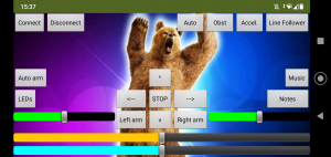
It is advised to include some text Labels to debug the app and a text box to send arbitrary commands to the robot and debug it, once the project is finished you can just make them invisible, like in the image above. Personalizing the app with photos and backgorunds is cool but it can increase a lot the size of the app, so it is better to do it last, once everything works correctl. The code at the end of the post includes this app without the image or icon, but you can grab them from google.
Sliders
The green sliders can be used to move the arms of the robot to an arbitratry position between 0 and 180 degrees.
The yellow one can change the velocity of the robot between 0 and 100, if the speed is to low the robot just stops.
The blue one is a special case, it only works when you press the “notes” button, and it allows us to play music with the buzzer of the robot. Moving the slider change the frecuency of the sound, pressing down the button send the command to the robot, and releasing it send a command that stops the sound. This allows us to play rudimentary music with the buzzer.
Movement Buttons
To move the robot there are five buttons, all of them send the same command: the letter ‘m’ in ascii and two values, the first specifies the linear movement and the later specifies the angular movement, these values are send in the 0/200 range, but are converted in the robot to the -100/100 range.
The left and right buttons are instantaneous and use a common variable, so both of them can be used at the same time without problem. They send a command when they are pressed and when they are released
The forward and backwards buttons are more complicated, when one of them is pressed, a variable changes and one of the clocks of the app increase and/or decrease the linear velocity and send the updated velocity to the robot. This way you have to press the button for a while but the robot continue its movement when you release it. To stop the robot you can use the other button to slow it down slowly or use the stop button, which just sends a command with 0 linear and angular velocity.
If you press the accelerometer button you can move the robot using the accelerometer, each time the clock fires, the app measures the accelerometer sensor, interpret and transform the measurement and send it to the robot. this way you can control the robot as if the phone were a wheel. This method has the problem that the phone is constantly sending commands while the robot moves, and the bluetooth interferes with the servomotors making them move strangely.
Other Buttons
The rest of the buttons are more straightforward and just send one letter to activate/deactivate some kind of behavior on the robot. The buttons at the top of the screen are used to detect and avoid obstacles and follow lines using the infrared sensor, whereas th buttons at the sides are for secondary functions like playing music, moving the arms or lighting up the led matrix. The matrix and the arms do different things depending on the direction of movement.
5. Programming the robot
All the program has been done using entirely the facilino blocks, although the program has some custom Arduino code that can not be used directly with the facilino blocks. One problem of facilino is that it starts to go very slowly when the program gets very large, using a more powerful computer could help.
The main part of the program is a huge switch case that executes something diferent depending on the command that it receives via Bluetooth. Some of the commands are send with additional values, those values are read immediately in the corresponding case. Some of the commands are used for debugging.
Commands
The most important command is the one that reads the linear and angular movement and applies them to the wheels, there is a special function used to move the wheels. This function can stop and disconnect the wheels when the movements are zero and it uses variables to inform if the robot is moving forward, backwards or turning, among other things.
Similar to the previous case we have one that reads a value and transforms it into a frecuency and activates the buzzer, this allows the robot to play arbitrary music (although it sounds bad). To implement this feature it was necessary to use custom Arduino code, it is very similar to one of the facilino buzzer blocks that lets you play generic tones, the main difference being that it doesn’t use delays, so the notes can be changed immediately and the robot can receive and execute other commands.
There are also two commands that read values to move the arms of the robot to arbitrary positions between 0 and 180 degrees, and two commands that move the arms to fixed positions alternatively
The other cases are used to activate or deactivate music and activate or deactivate different modes. These modes are controlled using interruptions
Interruptions
The interrruptions do two main things:
- Disconnecting the arms when half a second passes since the last time they were moved. This is very useful because if you don’t disconnect the arms they may move strangely when the robot receives bluetooth commands (which is all the time). This was implemented with custom code because the facilino alternative forces the robot to wait until the arm has stopped moving, this makes the robot unresponsive, which is not cool.
- Managing all the automatic behaviours: linefollowing, obstacle avoidance and automatic use of the arms and leds.
Line Following
When the line following mode is activated, an interruption will start reading the infrared sensor periodically and it will update the movements of the wheels. This feature is kind of difficult to implement, it requires a careful calibration to function perfectly, as the sensor is not sensitive enough for this task. But if you only want the robot to follow the line regardless of the movement’s smoothness it is not that difficult, you only need to make it move slowly, calibrate the white and black and use some of the blocks that facilino includes.
Obstacle avoidance
This robot has two obstacle avoidance modes, in both of them it uses the ultrasound sensor to measure the distance and it calculates a variable that reduces the linear movement of the robot and then, it updates the speed of the wheels. This way the robot starts to slow down when it aproaches an obstacle, if an obstacle is too close the robot will go backwards until it is at a medium distance again.
In one mode the robot just stops when it is at a medium distance of an obstacle, but in the other mode it turns around to avoid the obstacle. You can leave the robot alone in this mode and it will move around the room endlessly until it reaches some low/undetectable obstacle. The direction it turns can be changed with the same command that activates this mode.
Arms automatic movement and led matrix
The robot can move its arms and light different images in the led matrix depending on its movement, this behaviours can be activated/deactivated independently and are compatible with all the other modes.
To do this, we need to use an interruption and some variables that tell us if the robot is moving and in which direction it moves, then we use some if/else functions and some time counters and alternate fucntions to move the arms correctly.
When the robot doesn’t move, a cross appears in the led matrix and its arms move to the front. When it turns to the sides an arrow appears on the matrix and it moves one arm up and the other to the front, the arrow and arm position change depending on the direction of the turn. When the robot goes forward, a smile appears on the matrix and the arms quickly move back and forth above its head. Finally, when the robot moves backwards a sad face appears on the led matrix and the arms move slowly up and down in front of the robot.
6. Other Features
You can use BearBot to attack your pets, this is not nice, but is kinda funny.
7. Download
You can donwload the code of this project for the Android app and the robot. The app can be installed directly in an Andorid phone or edited with App inventor. The code of the robot can be opened and edited with either Arduino IDE or the Facilino software.