[:es]El propósito de esta entrada es indicar los pasos necesarios para lograr hacer un diseño CAD muy básico para representar el componente de comunicación bluetooth de vuestro robot.
Nuestro objetivo de diseño es lograr obtener un diseño CAD para el módulo bluetooth. Mencionar que este módulo irá colocado sobre la base del robot, sin ser necesario diseñar ningún elemento de fijación o soporte, ya que irá pegado. Por ello, utilizaremos la capa de grabado superficial simplemente para hacer marcas sobre la base que ayudarán a la posterior colocación del componente, pero en ningún caso es necesario hacer corte de material.
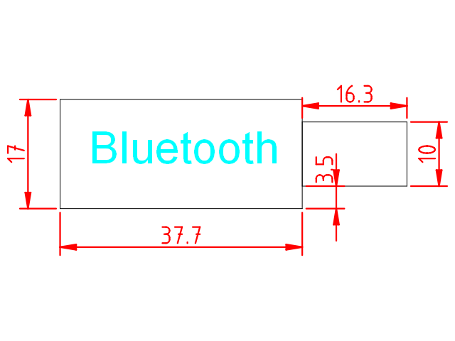
La medidas del módulo bluetooth son como se muestra a continuación:
A partir del fichero de plantilla para los componentes:
Seleccionamos la capa «Grabado Superficial» y creamos una polilínea con el siguiente conjunto de comandos:
polyline
0,0
@37.7,0
@0,17
@-37.7,0
@0,-17
Después creamos otra polilínea con el siguiente conjunto de comandos (también en la capa de grabado superficial):
polyline
37.7,3.5
@16.3,0
@0,10
@-16.3,0
Posteriormente en la capa de «Anotaciones», vamos a escribir un texto seleccionando la herramienta «Texto» del menú de herramientas (a la izquierda). Seleccionad la letra y tamaño de fuente conforme creáis conveniente (nosotros utilizamos Arial tamaño 5).
Finalmente podéis también añadir cotas, seleccionando la capa de Cotas, y utilizando las «Herramientas de dimensión» del menú de herramientas.
Aquí podéis descargar el fichero DXF con la solución:
[:en]The purpose of this entry is to indicate necessary steps to create a CAD design, very basic, to represent the bluetooth module (HC-06) of the robot.
Our goal is to obtain a CAD design of the bluetooth module. Usually, this module will be located at the robot base, not requiring any supporting element, since we will glue it. For that reason, we can create this component in the auxiliary layer to help the design of the rest of the robot, but in any case we won’t cut material to support it.
The dimensions of the bluetooth module are shown next:
We will use the following template:
Select «Aux» layer and create a polyline with the following commands:
polyline
0,0
@37.7,0
@0,17
@-37.7,0
@0,-17
After that, we create another polyline with the following set of commands (also in the Auxiliary layer):
polyline
37.7,3.5
@16.3,0
@0,10
@-16.3,0
Finally, we can write a text using the «Text» tool at the left-side menu. Select the letter type and size as you consider appropriate (we have used Arial size 5).
Also, you can add some dimmensions using the «Dimension tools» at the Tool’s menu.
Here, you can download the DXF file with the complete solution:
[:]