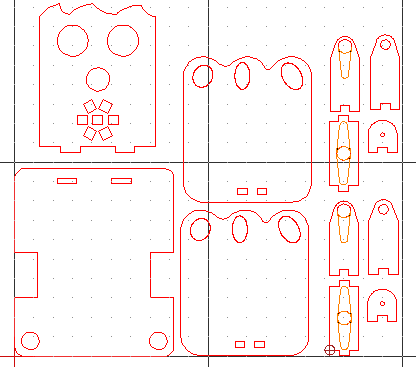
En esta entrada se muestra cómo diseñar el robot DYOR bPED con QCAD paso a paso (se trata de una versión simplificada de las piezas de corte láser del robot DYOR bPED disponibles en la tienda).
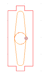
Nuestra propuesta para el diseño del robot DYOR bPED en 2D es como se muestra a continuación:
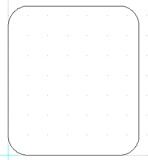
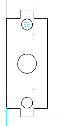
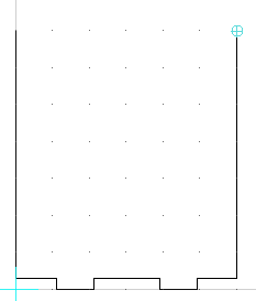
Diseño de la base
Crea un rectángulo de dimensiones (82,97) mm, posiciona la primera esquina en la coordenada (0,0) mm.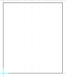
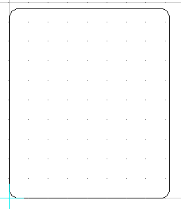
Ahora con la herramienta de redondeo [R,N] con un radio de 5 mm redondeamos las esquinas de la base:
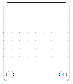
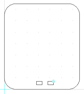
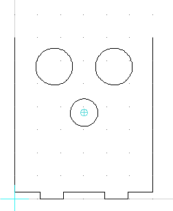
A 8 mm de distancia de los bordes, creamos dos círculos para pasar cables de radio 4.5mm. Los centros de los círculos están en las coordenadas (8,8) y (74,8) mm, respectivamente.
Crea dos rectángulos para los huecos de los servos de las patas. El primer rectángulo tiene como primera coordenada del punto esquina (0,30.4) mm y segunda coordenada del punto esquina (11.8,53.6) mm. El segundo rectángulo tiene como primera coordenada (70.2,30.4) mm y segunda coordenada (82,53.6) mm.
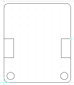
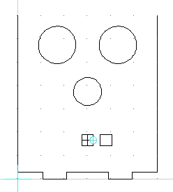
Ahora creamos los orificios para soportar la cara del robot. Los orificios son rectángulos de dimensiones (10,3) mm. El primer rectángulo lo posicionamos en la esquina a (22,89) mm del origen y la segunda esquina está en una posición relativa de @10,3 con respecto a la primera. Para es segundo orificio repetimos el procedimiento, cuya primera esquina está en (50,89) mm respecto del origen.
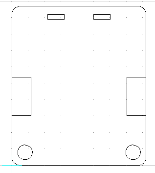
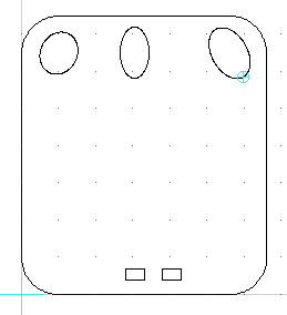
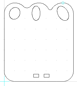
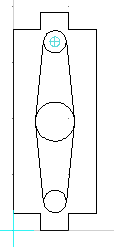
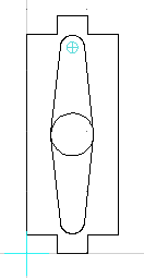
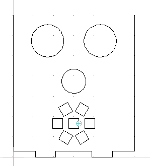
Ahora debemos eliminar las partes que no son necesarias para el corte por láser. Concretamente, eliminaremos los lados exteriores de los huecos de los servos. El objetivo es crear el perfil tal y como se muestra moviendo los puntos extremos de los segmentos tanto de la base como del orificio del servo.
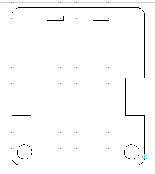
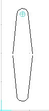
Finalmente pasaremos todos los elementos creados a la capa de corte y uniremos todas las líneas de la periferia, así como las de los orificios para soportar la cara en una única polilínea con el comando [O,G].
Diseño del pie
El diseño de los dos pies es idéntico con lo que proporcionamos las instrucciones para crear un pie (el otro es el espejo vertical).
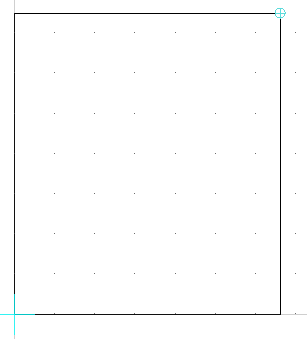
Crea un nuevo dibujo con un rectángulo de dimensiones (66,75) mm, posiciona la primera esquina en la coordenada (0,0) mm (posteriormente eliminaremos partes de este rectángulo).
Ahora con la herramienta de redondeo [R,N] con un radio de 10 mm redondeamos las esquinas del pie:
Ahora crearemos los orificios para soportar la pieza del tobillo del robot. Son dos cuadrados de dimensiones (5,3) mm. La primera esquina del primer orificio se posiciona en la coordenada (28,4) mm, mientras que la segunda esquina está en la coordenada (33,7) mm. Repetimos el procedimiento para el segundo orificio con las coordenadas (38,4) mm y (43,7) mm, respectivamente.
Ahora con la herramienta de crear elipses, procedemos a crear tres elipses en la parte delantera del pie. Su posición y tamaño no son relevantes en tanto en cuanto respeten los criterios necesarios para su fabricación:
Finalmente, podemos crear segmentos de arco que modifiquen el aspecto de los dedos de los pies. De nuevo, el tamaño y posición no es del todo relevante, pero sí que debemos asegurarnos que entre segmento y segmento de arco, los extremos son coincidentes, con lo que lo más sencillo es utilizar la opción de crear segmentos de arco a partir de tres puntos, en el que podemos sencillamente especificar el punto inicial, un punto intermedio y un punto final.
Ahora podemos pasar todos los elementos a la capa de corte. Recordad que podéis unir todos los segmentos de línea y círculo con el comando Crear a partir de segmentos [O,G].
Diseño de la pierna
La pierna está compuesta por tres piezas: la parte delantera a la que se atornillará la manilla del servo del pie, la parte trasera en contacto con la pieza del tobillo y que acomodará un rodamiento y la parte superior a la que se atornillará la manilla del servo de la pierna. Las tres piezas forman una «U» que envuelven al servo del pie una vez ensambladas.
Parte delantera
Primero creamos una polilínea con las siguientes coordenadas:
0,27
@0,-27
@5,0
@0,3
@5,0
@0,-3
@5,0
@0,27
Ahora creamos un círculo de radio 5mm con centro (7.5,33.5) mm:
Ahora creamos dos rectas tangentes al círculo cuyo punto inicial es cada uno de los extremos de la polilínea:
Para eliminar la parte del círculo que no pertenece a la periferia, utilizamos la herramienta Partir [D,I], seleccionamos el círculo y buscamos los puntos de intersección. Una vez partido el círculo, podemos proceder a eliminar el arco sobrante.
Ahora creamos un círculo de radio 3.5 mm con centro (7.5,33.5) mm.
y otro círculo más pequeño de radio 2 mm con centro (7.5,19) mm.
Para generar la forma de la manilla del servo, crearemos dos rectas tangentes a los círculos.
Ahora crearemos un segmento de círculo con radio 3.5 mm y puntos extremos en las intersecciones de las rectas recién creadas. Este segmento de círculo aparece seleccionado para resaltarlo en la imagen.
Finalmente, partimos el círculo pequeño en dos por los puntos de tangencia con el comando Partir [D,I].
Ahora, es conveniente mover los objetos de la periferia a la capa de corte y los elementos de la manilla del servo (incluyendo el segmento de círculo creado a la capa de grabado superficial).
Recordad que podéis unir todos los segmentos de línea y círculo con el comando Crear a partir de segmentos [O,G].
Parte trasera
A partir del diseño anterior, ahora debemos primero eliminar los elementos internos y crear un círculo con centro (7.5,33.5) mm y radio 2.45 mm para el rodamiento. Pasamos todos los objetos a la capa de corte y creamos todos los segmentos de línea y círculo como una única polilínea.
Parte superior
Creamos una polilínea con los siguientes comandos:
0,3
@5,0
@0,-3
@5,0
@0,3
@5,0
@0,33
@-5,0
@0,3
@-5,0
@0,-3
@-5,0
@0,-33
Ahora creamos tres círculos: el primero con centro (7.5,19.5) mm y radio 3.5 mm; el segundo con centro (7.5,5.2) mm y radio 2 mm y el tercero con centro (7.5,33.8) mm y radio 2 mm.
Ahora creamos cuatro segmentos de línea tangentes a los círculos tal y como se muestra:
Ahora partiremos (con el comando Partir [D,I]) en los círculos pequeños en los puntos de tangencia y eliminaremos el segmento de círculo sobrante. Recordad que en el punto de división, debemos colocar el cursor en el punto que detecta como «intersección».
Ahora, para evitar confundirnos, lo más sencillo es pasar la polilínea y el círculo central a la capa de corte y ocultar temporalmente esta capa.
Creamos otro círculo con centro (7.5,19.5) mm y radio 3.5 mm al igual que antes y partimos el círculo en cuatro partes en los puntos de tangencia con las rectas y eliminamos la parte sobrante de los laterales y pasamos todos los elementos a la capa de grabado superficial. El resultado final uniendo las polilíneas con el comando Crear a partir de segmentos [O,G] es como el que se muestra:
Diseño del tobillo
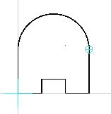
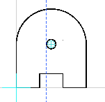
El tobillo es simplemente una pieza de soporte en la que se inserta un remache que atravesará el rodamiento que está colocado en la pieza de la pierna de la parte trasera. Primero empezaremos creando una polilínea con los siguientes comandos:
0,9.3
@0,-9.3
@5,0
@0,3
@5,0
@0,-3
@5,0
@0,9.3
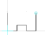
Ahora creamos un segmento de círculo a partir del radio (7.5 mm) y dos puntos (los extremos de la polilínea).
Finalmente crearemos un círculo de radio 1 mm y centro (7.5,9.3) mm.
Ahora podemos pasar todos los elementos a la capa de corte. Recordad que podéis unir todos los segmentos de línea y círculo con el comando Crear a partir de segmentos [O,G].
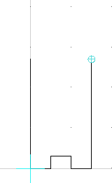
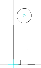
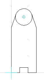
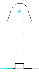
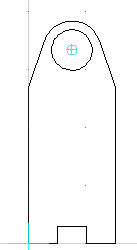
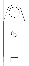
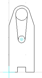
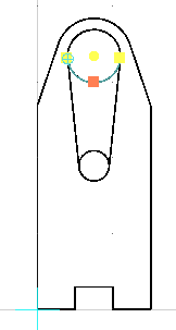
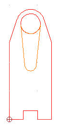
Diseño de la cara
Empezamos creando una polilínea:
0,70
@0,-67
@11,0
@0,-3
@10,0
@0,3
@18,0
@0,-3
@10,0
@0,3
@11,0
@0,67
Los orificios para el sensor de ultrasonidos son dos círculos de radio 8 mm, cuyos centros son (17,57.5) mm y (43,57.5) mm, respectivamente. Por otro lado, el orificio para el zumbador es un círculo de radio 6 mm con centro (30,37.5) mm.
Para los orificios de la tira de leds con forma redonda que hace de «boca» crearemos un cuadrado de 5×5 mm (para el led central). La primer esquina del cuadrado del LED del centro está en la coordenada (27.5,14.1) mm, mientras que la segunda esquina está en la coordenada (32.5,19.1) mm. Luego, seleccionamos el cuadrado recién creado y realizamos una copia [M,V] e introducimos como punto de referencia cualquier esquina del cuadrado y como punto objetivo @8,0, es decir, el cuadrado estará desplazado 8 mm a la derecha (aseguraros que al hacer la copia no borráis el elemento original). Para poder ahora hacer copias giradas de este nuevo cuadrado, primero crearemos una línea auxiliar entre los puntos medios del cuadrado central (tanto horizontal como vertical), ya que el objetivo es utilizar el punto de intersección como punto pivote.
Ahora estamos en disposición de seleccionar el cuadrado de la derecha y realizar una copia múltiple girada 60º. Con el cuadrado seleccionado introducimos el comando de rotar [R,O] y marcamos como punto central el punto de intersección del cuadrado central y marcamos la opción de copia múltiple con 5 copias giradas 60º. Ahora ya podemos eliminar las líneas auxiliares que hemos creado en el cuadrado central
Para finalizar, podemos dibujar de forma sencilla un pelo de forma que, al igual que se ha hecho con los pies, el objetivo es dibujar segmentos de círculo conexos a partir de sus puntos.
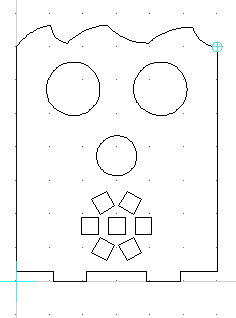
Ahora podemos pasar todos los elementos a la capa de corte. Recordad que podéis unir todos los segmentos de línea y círculo con el comando Crear a partir de segmentos [O,G].
Nota
En la versión básica del robot bPED, la tira de 7 LEDs redonda no se incluye porque este robot está pensado en se controlado directamente desde Arduino Nano que trabaja a 5V, mientras que el robot bPED (completo) utiliza el procesador ESP32 que trabaja a 3.3v, aptos para la tira de LEDs.
El diseño de la versión básica es por tanto muy similar al de la versión completa con la principal diferencia que en la versión básica la cara es 29.8mm más pequeña. La base del robot también es 21 mm más pequeña (de largo), ya que no necesita tampoco acomodar un powerbank, si no que utiliza una batería de 9V en su lugar.