[:es]El propósito de esta entrada es indicar los pasos necesarios para lograr hacer un diseño CAD muy básico para representar la matriz de LEDs 8×8 de vuestro robot.
Nuestro objetivo de diseño es lograr obtener un diseño CAD para la matriz de LEDs 8×8 basado en el módulo max7219. Mencionar que este módulo irá colocado sobre la parte frontal del robot, siendo necesario realizar un orificio cuadrado para los LEDs visible desde la parte frontal, yendo el resto de la electrónica en la parte oculta del frontal, que irá pegada a el. Por ello, utilizaremos la capa de corte para el cuadrado y la capa de grabado superficial simplemente para hacer marcas sobre el frontal con la forma de la electrónica para la colocación del componente.
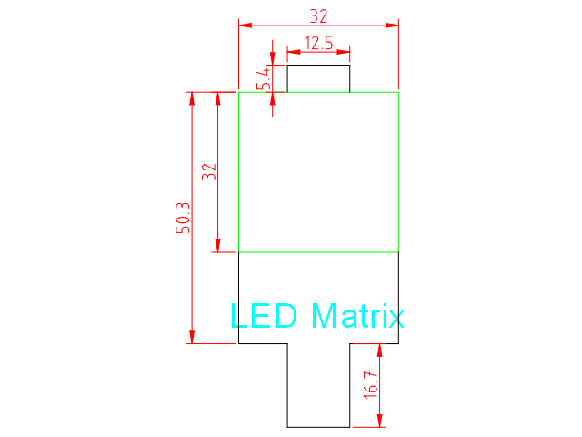
La medidas de la matriz de LEDs 8×8 son como se muestra a continuación:
A partir del fichero de plantilla para los componentes:
Seleccionamos primero la capa «Grabado Superficial» y creamos una polilínea con forma de «T» (empieza en la parte inferior de la esquina del cuadrado verde):
polyline
18.3,0
@0,-18.3
@9.75,0
@0,-16.7
@12.5,0
@0,16.7
@9.75,0
@0,18.3
Después creamos otra polilínea con forma de «U» invertida en la parte superior:
polyline
9.75,50
@0,5.4
@12.5,0
@0,-5.4
Finalmente creamos una polilínea con forma de cuadrado en la capa de corte:
polyline
0,18.3
@32,0
@0,32
@-32,0
@0,-32
Posteriormente en la capa de «Anotaciones», vamos a escribir un texto seleccionando la herramienta «Texto» del menú de herramientas (a la izquierda). Seleccionad la letra y tamaño de fuente conforme creáis conveniente (nosotros utilizamos Arial tamaño 5).
Finalmente podéis también añadir cotas, seleccionando la capa de Cotas, y utilizando las «Herramientas de dimensión» del menú de herramientas.
Aquí podéis descargar el fichero DXF con la solución:
[:en]The purpose of this entry is to provide with a CAD design and the necessary steps to represent the 8×8 LEDs matrix of the robot.
Our design aim is to obtain a CAD design for the 8×8 LEDs matrix including the module with the max7219. This module will be placed at the robot’s face, so we need to create a square with the size of the LEDs matrix itself, which will be the visible part. The remainder of the electronics, will be at the rear part and glued to it. We will use the cutting layer of the square and the rest of elements will be drawn in the auxiliary layer.
Dimensions of the 8×8 LEDs matrix are as shown:
We will use the following template:
Select the Auxiliary layer and create a polyline with a «Y» shape (starting at the bottom side):
polyline
18.3,0
@0,-18.3
@9.75,0
@0,-16.7
@12.5,0
@0,16.7
@9.75,0
@0,18.3
Then, we will create another polyline with the «U» shape (inverted):
polyline
9.75,50
@0,5.4
@12.5,0
@0,-5.4
Finally, we will create another polyline with the square in the cutting layer:
polyline
0,18.3
@32,0
@0,32
@-32,0
@0,-32
We can annotate dimensions and text in the auxiliary layer as shown, using the corresponding tools.
Here you can find the DXF file with the solution:
[:]