The purpose of this entry is to show necessary steps to create a CAD design to represent the ultrasound sensor HC-SR04 of your robot.
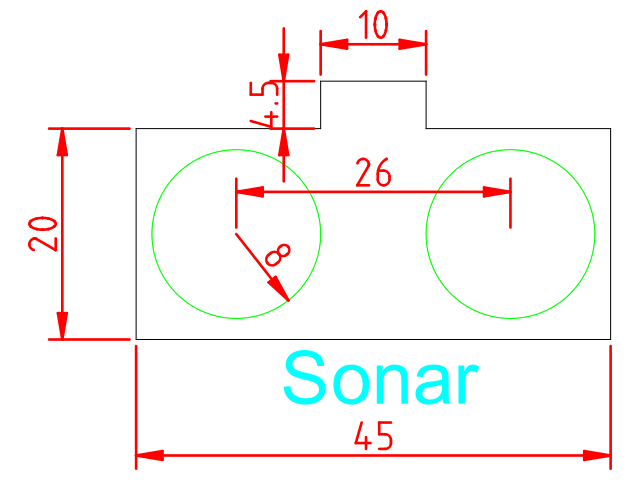
Our design aim is to obtain a CAD design for the range distance module based on the HC-SR04 ultrasound sensor. This sensor is part of the robot’s face, so we require two holes of 8mm radius to fit the caps of the sensor. Once insice, the ultrasound sensor will be glued to the face (on the back side). We will use a cutting layer for the holes and and an auxiliary layer for the shape of the sensor.
Dimensions of the sensor are shown below:
We will use the following template:
Select the auxiliary layer and create a polyline with the following commands:
polyline
0,0
@45,0
@0,20
@-17.5,0
@0,4.5
@-10,0
@0,-4.5
@-17.5,0
@0,-20
Afterwards, create two circles in the cutting layer:
circle
9.5,10
8
circle
35.5,10
8
Finally, we can add dimensions and text on the auxiliary layer by selecting the appropriate tools on the left-side menu.
Here, you can find the DXF file with the solution: