This post will briefly explain how the robot RAMBOSO was assembled and programmed.
Some of the functions he can do are:
- present himself in a glorious way
- shoot to everything that appears in front of him
- path patrolling (line following and send messages with the gun ready to shoot)
- avoid obstacles
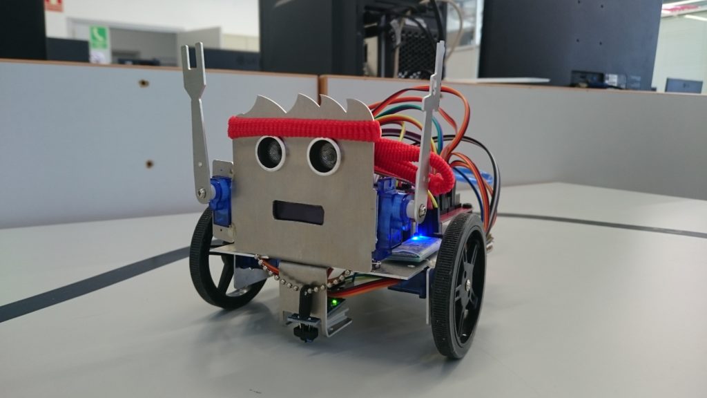
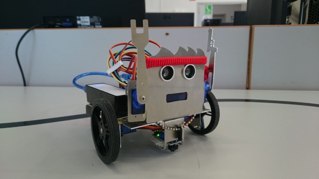
MATERIALS and COMPONENTS:
- metal structure
- continuous servos FS90R with wheels (2)
- servos SG90 with metal arms (2)
- Arduino Nano
- power bank
- OLED display 128*32
- RGB LEDs
- line tracker
- Bluetooth
- sonar
- buzzer
- cables
- caster wheel
- scotch tape and insulating tape
- screws and screwdriver
- hair bands
- 3D printed plastic plate and metal bracelet
PROCEDURE
ASSEMBLY
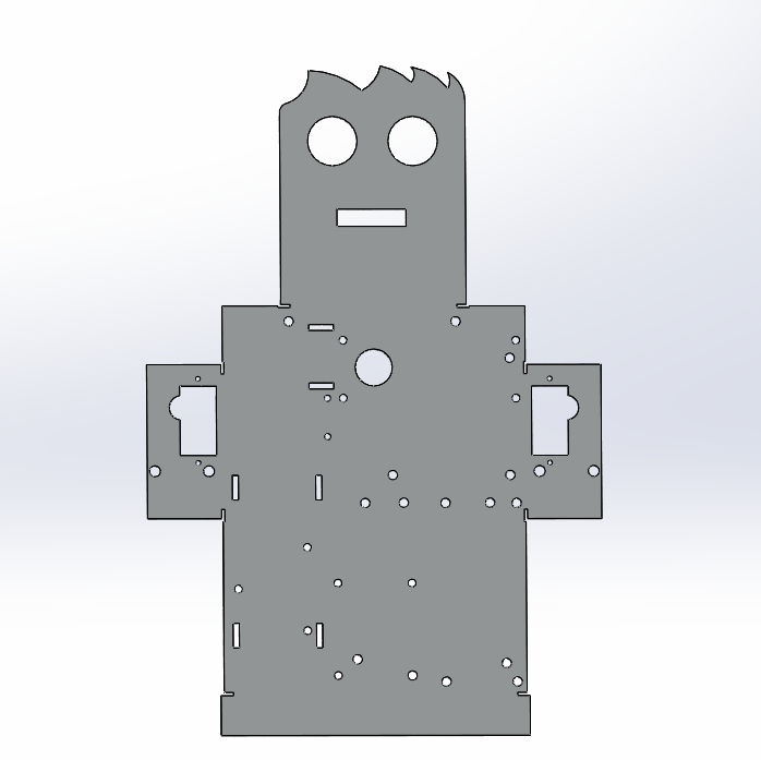 The physical construction of the robot started with the bending of the metal foil that became then the structure of the same. The foil shown here in the CAD model is ready to be used with M3 screws and the components listed above.
It is possible even to see the parts that had to be bent: head, lateral supports of continuous servos, and the rear part that became the support for rear LEDs.
Then it was necessary to choose the place for each component.

As can be seen in this picture the holes of the face are ready for the positioning of sonar (eyes) and OLED display (mouth).

On the other side, this picture shows the components: Bluetooth and buzzer on the left close to the wheel, sonar and OLED in the centre, between the servos
On the right, it was positioned the power bank, in white.
Everything was fixed with screws and double-sided tape.

Under the foil can be found the continuous servos with the infrared sensor, necessary for line following processes.
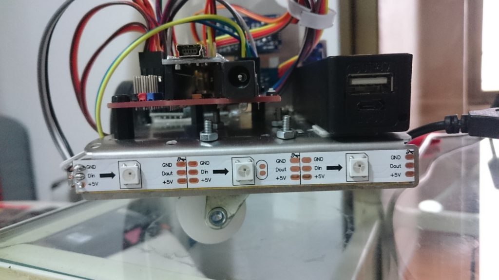
On the back, it was positioned the row of RGB LEDs.
These needed soldering of the contacts with the cables, the only way possible to connect them with Arduino.

All the components were then connected to the Arduino Nano with cables as shown here.
Depending on the function needed, there are digital and analogical pins available on Arduino. Even if analogical can be used as digital too. The difference is necessary for some applications like the reading of some sensors. Here for example an analogical one was used for the infrared sensor.
The last step was the upload of the code and the connection with the power bank with a USB cable.
FACILINO and ARDUINO IDE
After the assembly part was finished, was necessary to program Arduino. This was possible with the block diagram that can be found on the webpage: https://roboticafacil.es/facilino/blockly/Facilino.html
The block diagram used is quite easy and fast to be understood and gives a quick introduction to this world to those who do not have much experience with programming and Arduino as well.
As can be seen in this picture

representing one of the basic blocks, there are two parts. The setup one where it is possible to insert commands that the creator wants to be seen just once. While in the setup part it is possible to insert commands that have to be read more times, in loop indeed.
Facilino has blocks for each of the components available and with a license, it is possible to use more functions with respect to the basic version.
Once the block diagram is completed, it is necessary to upload it to the Arduino hardware. This is possible thanks to the Arduino IDE program.
The steps are the following ones:
- creation of a blocks diagram with Facilino
- copy it to Arduino IDE
- upload of the code to Arduino hardware
Once the Arduino (hardware) receives the code is ready to be used. This is indicated by two green lights positioned on top of the Arduino.
APPINVENTOR 2
After the programming step, it was necessary to create an app that could send commands via Bluetooth to control the robot. This was possible thanks to AppInventor 2, made by MIT and available simply by logging in with a Google account at: http://ai2.appinventor.mit.edu/
This webpage allows users to create an App in a quite fast and simple way, using a block diagram like Facilino. After logging in, it is necessary to choose the option “start new project”.

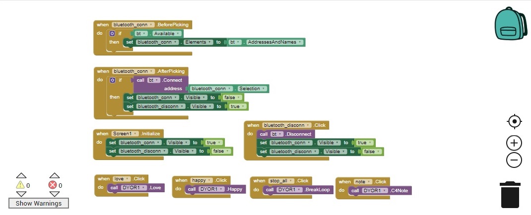
As can be seen in the images, there are two parts in a project:
- designer – area dedicated to the creation and management of the graphic part
- blocks – an area dedicated to the creation and management of the commands
The first step is the creation of buttons, with different shapes and colors in the designer area. It is possible to use pictures and icons as well instead of the normal text.
Once the graphic part is completed, it is necessary to decide which command each button sends and this can be done in the other area. Here block diagrams, like the ones already seen, are used. It is possible to choose many options and features, like the buttons that appear with the App initialization, command sensibility, etc. It is possible to include also an accelerometer, reproduction of sounds, and videos on the phone.
The application sends via Bluetooth bytes that Arduino receives and reads as commands. In Facilino there is a list of all the existent commands. It is important to know that the possible bytes which can be sent are 256, from 0 to 255. Moreover, it is possible to create commands only by sending the byte that corresponds to that specific instruction indicated in the Arduino code.
In this picture it is possible to see the Ramboso app with its commands and tasks:
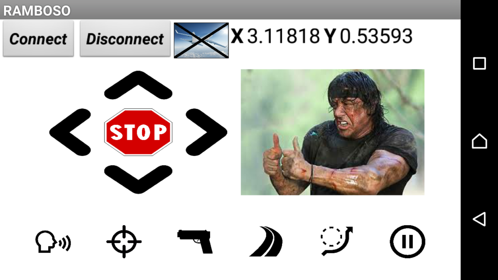
- basic movements with buttons
- basic movements with accelerometer and values of acceleration in x/y directions
- voice and sounds reproduction
- arms movement
- line following
- obstacle avoidance
- Bluetooth connection/disconnection
- “Mission complete” (the text on display, colored LEDs, sounds, movements)
PRACTICE
In these YouTube videos, it is possible to see a practical demonstration of the described robot.
Thank you for your attention!