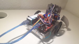
In this blog post, the Arduino-controlled robot BOOot is presented. The post will include a brief look into the design, assembly and programming of the robot.
DYOR BOOot
Components
- Arduino Nano + Shield Arduino Nano I/O
- Powerbank
- Mini-USB cable
- Ultrasound HC-SR04
- Buzzer
- Servos SG90 (blue) in the base
- Servos FS90R (blue) in the base
- Bluetooth
- OLED
- Linetracker TCRT5000
- Caster wheel
- FS90R wheels
- Jumper cables
- Metalsheet
- Arms
- Zip ties
Design of BOOot
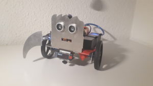
The design of the robot was done in Solidworks. The parts and assembly of sample robots was provided. I changed the appearance to the ghost emoji 👻 to make my robot scary.
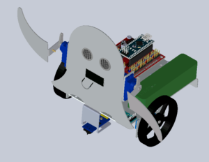

The metalsheet and arms were exported as DXF files for cutting it by laser. Sadly the metalsheet could not be manufactured and I got the standart robot.
Assembly
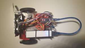
First I connected all components with jumper cables to the arduino to test them and understand how they work. The rear LED strip had to be soldered to jumper wires to connect to the arduino. Then I bent the metalsheet. It was hard to get a clean bend at the edges. The connection between arms and head were very fragile so one arm broke while bending.
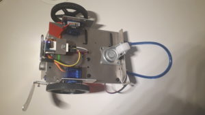
Afterwards all components were fixed with screws, zip ties and hotglue on the metalsheet. In the end the components were connected with jumper cables to the arduino. The rear LED strip had to be soldered to jumper wires to connect it to the arduino. I did a mistake while rewiring so the nano started but no code was executed. After checking everything and finding the mistake everything worked.
Programming
Facilino and Arduino IDE was used to program the robot, MIT App Inventor was used to create an android app to control the robot. App Inventor and Facilino are both programming tools that use Blocks that you can drag and drop. So you can start without much prior programming knowledge to develop your robot but the tools are limited. Luckily you can copy the Facilino code and enhance it in Arduino IDE.
I won’t cover the basics of the programs because there are good tutorials out there. I focus on difficulties that I encountered and how to solve them.
MIT App Inventor
With MIT App Inventor you can easily create an android app while live testing it on your phone.
Design
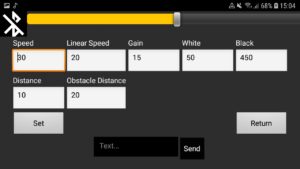
For my app I designed to screen. One to control the robot and another one to change settings of the robot. Creating the layout takes some time because it’s not really intuitive in the beginning. All the elements can be easily added and edited.

Functionality
The phone can connect via bluetooth with the robot. It is possible to send commands to move the robot or start autonomous behaviour. Furthermore data can be send to the robot for settings like speed or distance.
Arduino
I used Facilno in the beginning to generate code fast and easy. It provides a wide range of blocks that is normally enough to build the robot. While developing the linetracking I wanted to set different variables per app. So i don’t have to upload the code again to the arduino for a parametric study which takes quite a while. There I started to use Arduino IDE because I reached the limit of Facilino.
Data connection between phone and robot
There quite a few challenges to overcome to transmit data to the robot. First of all, I had to differentiate between simple commands, like move forward, and data transmitting commands, like set the speed.
The data gets transmitted bytewise. This means that only numbers between 0 and 255 can be sent. For most applications this was no problem, but the value for black ground of the infrared sensor is normally around 450. App Inventor can send 2 byte numbers but on arduino you have to put the 2 byte number together again by multiplying the second byte with 256 and then adding both bytes.
For transmitting accelerometer data there are two steps necessary. The accelerometer data is provided in float which has to be rounded to integer before sending. The maximum value is 9,81 so I multiply the forward movement by 10 and the turn speed by 5 before rounding to get the speed in a range of -100 to 100 with a higher accurancy than when rounding before. Furthermore the speed must be offset because otherwise negative values will be transmitted as 256 + (negativ value) and the robot starts to furiously move forward or turning instead of standing still.
It is also possible to transmit text. Therefore the inserted characters are matched to their ASCII values, which are 1 byte, in the app and transmitted as 1 byte numbers. On the arduino side the bytes are interpreted as characters.
Functionality
Movement Control
The robot’s movements can be controlled via bluetooth. With my android app I can move the robot with the arrows on the control screen. Furthermore the movement can be controlled with the accelerometers of the phone. In both cases the robot moves in 5 different cases: forward, backward, left, right and stop which get indicated in the app.
After I established the data connection between the app and the robot I implemented a smooth accelerometer control. There the phone transmits the values of the accelerometers instead of just the different case. So the robot can do smooth turns. Before is was rather hard to get the robot to face in the desired direction.
Linetracking
The infrared sensor can differentiate between a black line and the normal floor. I implemented a live display of the infrared sensor value on the OLED display to set them accordingly on the robot. The calibration can be easily done with the app. So the linetracking feature can be easily used on different grounds or in different conditions.
Obstacle Avoidance
The robot can avoid obstacles. The distance is measured with the sonar sensor. So it works best when the object has a face that is perpendicular to the direction the robot is moving. After sensing an object the robot stops, turns for a random amount of time left or right and continues to move forward. The critical distance can be set in the app and is displayed on the OLED.
Distance Keeping
The robot can keep the distance to an object. The sensor delivers stable until around 40cm. This is the limit for detecting an object. After detection the robot moves to the distance that was chosen in the app. I use a P-Controller to control the speed of the robot. The robot turns because the servos are not well adjusted.
Displaying Text
The robot can display text that is sent per app. The app has to encode the message in ASCII and send it bitwise to the robot. So sadly there are no emoji on the screen possible.