In this post entry we explain our mobile robotics work assigment.
The Design of the robot
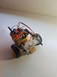
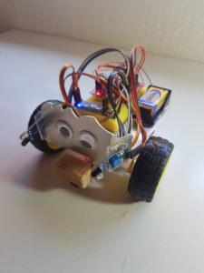
We assembled the robot by our own by buying the parts separately. Our robot consists of:
- Two steerable wheels with motors (no servomotors) and a caster wheel
- Two infrared sensors (obstacle detection)
- IR line following module (TCRT5000)
- Aluminium plate
- 9V battery
- Connection Cables
- Bluetooth module (initially an LE module, later we switched to a regular one)
- Arduino Nano (v 3.0), adapter (I/O extension shield) and a motor driver (DRV 8833)
- Sponges/ styropor: Necessary to avoid direct contact of the electronics with the aluminium plate. This can cause the Arduino to reset its entire code!

Functions
- Driving and Steering
Our robot is steerable in all directions. Either by pressing the buttons in the app, or by using the built in accelerometers of a smartphone. The robot performs its movements via the buttons as long as a button is pressed. Also the speed is adjustable with a slider in the application, however the type of motors we had are not easily adjustable in their speeds with analogue signals. We would rather recommend sticking to servo motors unless higher speeds are desired.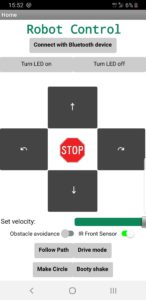
- BT Connection
At first we connected the Arduino to an low energy (LE) Bluetooth module. This caused a lot of problems, because it is very tricky to connect it properly to the MIT App inventor. Additional extensions are needed as well as searching for specific data of the module such as the UUID and mac-adress. Even after making the connection work, it failed on the next day. Before implementing more sophisticated functions, we tried to just make the built-in LED of the Arduino nano blink with our app. This worked sometimes, but not always, so that we can not recommend the use of a low energy module at all. We switched the type of BT module, which made everything work after. The BT connection can be checked via the App by pressing a button to turn the LED on and off. - Line following
Since we only had one sensor available at the bottom, it was not that easy to successfully implement a line following algorithm. The way ours works is, that the robot is placed on a line and drives forward as long as he detects the line. As soon as he diverges, he performs left and right turns to find the line back, so that he can follow her again. Since we did not have servo motors this task was not successful, because ours steered way too fast. Even when the robot detected a line, he surpassed it way too quickly because the motors advanced him too much. This caused the robot to flicker around in a seemingly random fashion. Obviously by using only one sensor, another problem arises: How does the robot know in which direction he leaves a line? We did not account to this directly, rather the idea is to turn left or right by a small amount after leaving the line to find it back. For smooth curvatures this should work better than for sharp corners. - Obstacle Detection
The two IR sensors make the robot stop in case of an obstacle in its front. While an object is being measured, the robot can only be steered backwards. Also an automatic obstacle avoidance mode can be activated via a switch in our app. Thereby the robot follows an hardcoded sequence to drive around an object roughly its size. Further calibration would be needed here, due to the difficulty in controlling the motors for small speeds.
- Specific Movements
- Dance
A sequence of movements is performed that make the robot “dance”. We implemented this in order to stop the line following when it is not possible to find a line.
- Circle
We tried to help the robot finding back the line after he diverged from it, by making it drive a circle.These two movements were initially part of bigger functions, but can be activated directly via the app.
- Dance
- Falling down avoidance
When the robot is placed on an elevated surface, such as a table, it can detect an edge with the bottom IR sensor. If the robot is steered towards and over this edge, it stops immediately and drives backwards, preventing the robot from falling. - Switching off the sensors
Because one of our sensors stopped working properly during the development phase, we included the option to let the robot ignore the sensor data by a switch in the app. Another reason to turn them off is the disturbance due to light effects. The IR sensor not detecting a clear contrast might lead to flickering and unwanted behaviour such as stopping.
Conclusion
To summarize, our objective was to build a low cost custom robot. We learned a lot about how sensors and modules of an arduino work, especially in what is practical and what not. For example for a line tracker one should use more than one sensor. Furthermore one should pay attention to the light situation in the surrounding when working with IR sensors. For the bluetooth connection a low energy module is not advisable due to the difficulty of connecting it with a phone. Lastly one should rather use servo motors when precise movements are required, because speed is better adjustable. The only advantage our motors had was the higher speed.
All in all if we could start all over with the knowledge we have now, we would stick to the part lists of the pre-arranged dyor robots of the shop, when it comes to selecting the parts. This can save you a lot of time and even some money 😉
Authors
Leona Schild and Dominik Schönhofen