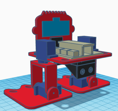
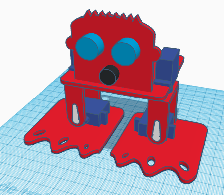
In this entry, we show the assembly of DYOR bPED Basic designed with TinkerCAD for 3D Printing.
Components:
- Arduino Nano I/O Shield (sand)
- Battery holder (black)
- Ultrasound HC-SR04 (light blue)
- Buzzer (black)
- SG90 Servos (dark blue)
- Ball bearing and rivet
Instructions:
We will distinguish between the servos required for the feet and the servos required for the legs. Also, we will distinguish between the servo horns required for the feet and the ones required for the legs.
We will distinguish between the servos required for the feet and the servos required for the legs. Also, we will distinguish between the servo horns required for the feet and the ones required for the legs.
IMPORTANT: When assembling the robot, the servos must be in 90º position, so that the “Home” configuration is the one shown in the assembly. The next program will allow you to position the servos at 90º (connecting them at the right pins).
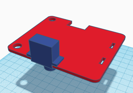
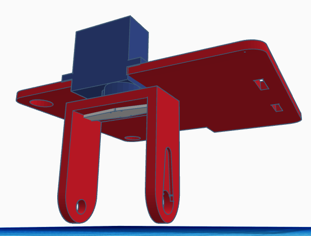
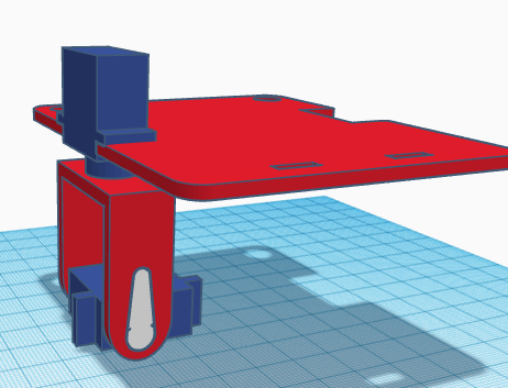
First, pass the servo through its corresponding hole at the base (pointing downwards) and with the axis centred.
Now, we need to fix the leg servo with its servo horn (double-sized). The servo horn must be cut at the ends so that it fits inside the leg. When screwing the horn, be careful in not rotating the servo axis. Once is fixed, it is not recommended moving the leg since the motor can be damaged.
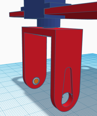
Afterwards, we need to assemble the legs by inserting the ball bearing for the ankle at the corresponding hole.
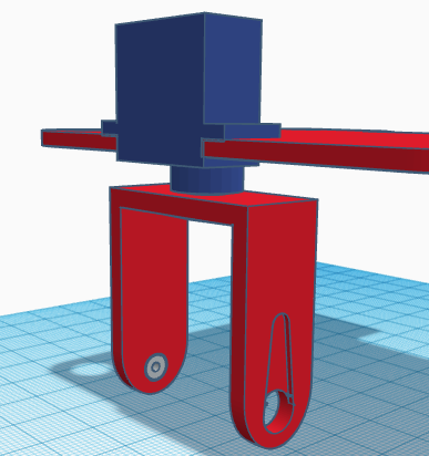
The rivet will be inserted from the inner side of the leg so that once we put inside the leg the foot servo, the rivet doesn’t fall apart.
Now, screw the servo to the horn (simple). Make sure you place the servo at the correct orientation (as shown in the assembly). The servo horn will be visible from the front side. Be careful in not rotating the servo before screwing it.
Once fixed, we can glue it to the foot.
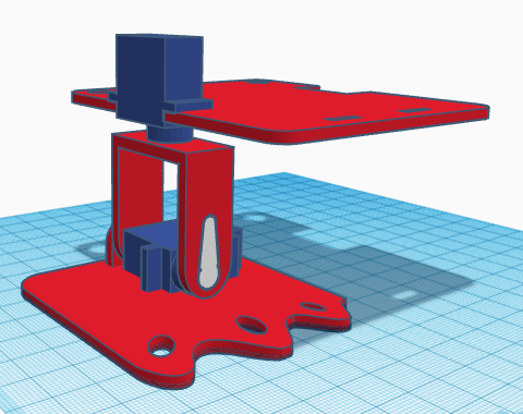
Repeat this procedure to assemble the other foot.
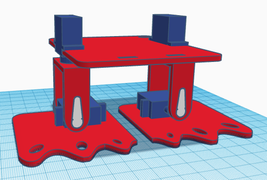
The ultrasound sensor and buzzer are glued directly to the robot’s front. The robot’s front is also glued to the base.
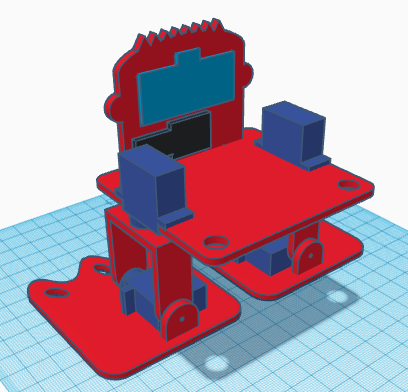
The electronics and battery holder are also glued to the base. The electronics is glued on top, while the battery holder is glued under.