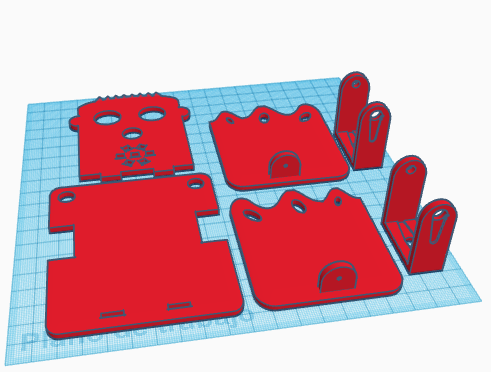
In this entry, we describe the process to design in TinkerCAD the robot DYOR bPED.
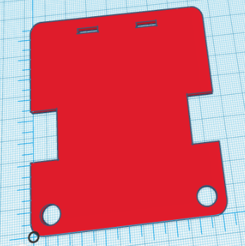
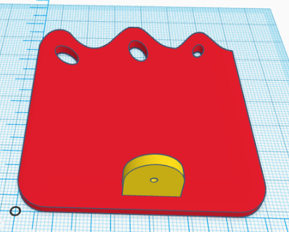
The expected result after finishing these steps is shown below:
First, we will download some necessary STL files to create holes for our components:
Base Design
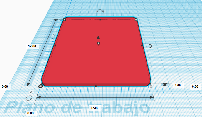
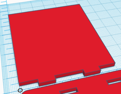
We will start by adding the ruler to our workplane. Put it somewhere close to the left-bottom corner of the workplane. After that, we need to create a cube with dimensions (82,97,3) mm and place it at the coordinate (0,0,0) mm with respect to the ruler. We also need to change the “radius” property to 1.22 mm to create rounded corners.
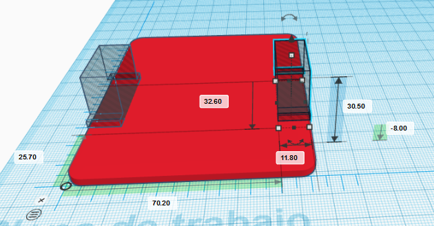
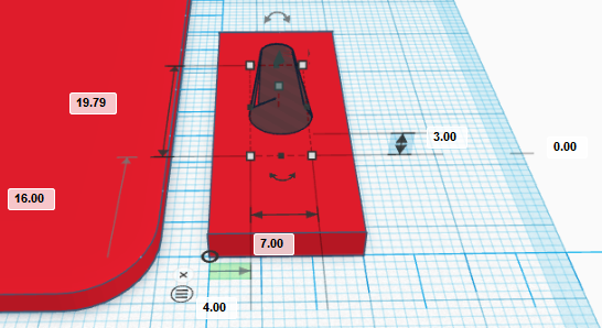
Import the file “Servo.stl” and place it at coordinate (0,25.7,-13) mm, turn it 180º so that the axis points downwards and select the hole shape.
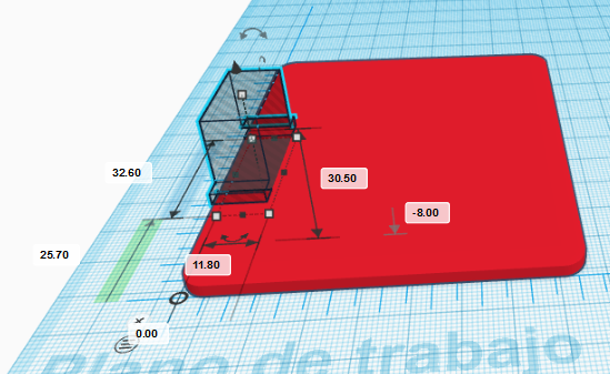
Now, we will repeat this procedure with the other servo by placing it at the coordinate (70.2,25.7,-8) mm, also with the servo axis pointing downwards and hole shape.
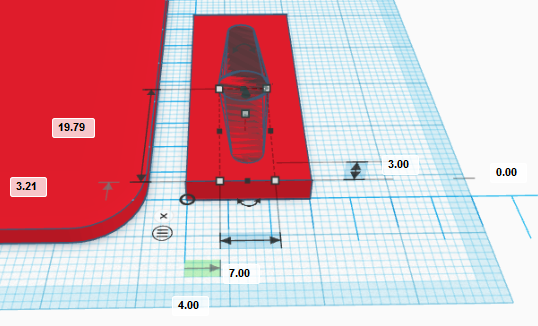
Now, we will create a cylinder of dimensions (9,9,3) mm and place it in the coordinate (3.5,3.5,0) mm. The shape will be a hole so that servo cables can pass through it.
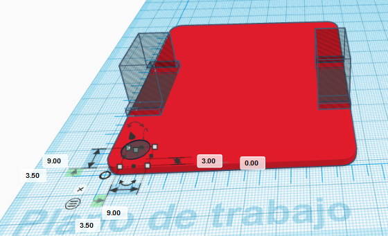
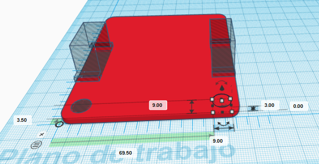
In the same way, we will create another cylinder with the same dimensions and place it in the coordinate (69.5,3.5,0) mm so that cables from the other leg can pass through too.
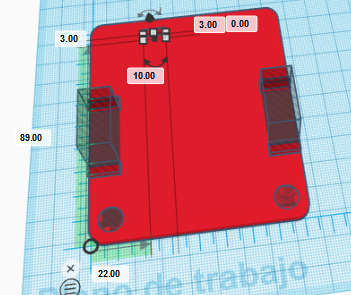
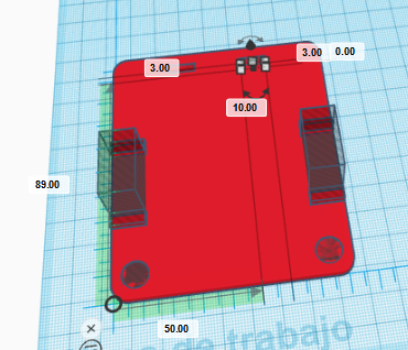
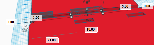
Now, we will create the holes to fit the robot’s front part. They are two cubes with dimensions (10,3,3) mm placed at coordinates (22,89,0) mm and (50,89,0) mm, respectively.
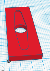
Finally, we will group all shapes to generate the part to print.
Feet Design
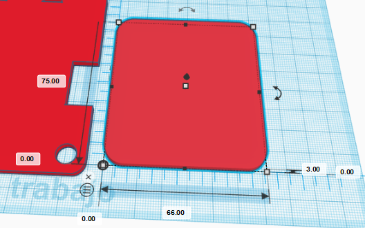
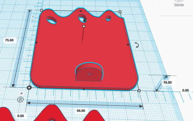
Now, we will move the ruler to the right, where we will start creating a robot foot. If necessary, you can move the already created base part to the left to leave more space. In order to design the left foot, we will create a cube with dimensions (66,75,3) mm placed at coordinate (0,0,0) mm with a rounding radius of 2.44.
In order to generate the feet, we will use an advanced feature of TinkerCAD in combination with Inkscape. The aim is to create a shape that we will use to remove part of the cube we have created so that we have three toes.
First, we need to draw, in Inkscape, a Bézier curve with an approximate size of 66×25 mm (make sure you are using mm):
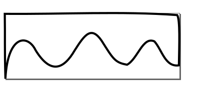
This is the file we have used:
After that, we need to create our own shape in TinkerCAD based on extrusion (which means that from a 2D shape, we will create a 3D shape by providing a proper height). Please, follow the instructions as given:
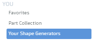
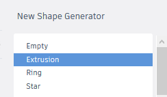
Once we are in the Shape Generator tool, by default it will be shown a circle. In the left side menu, we can manage our “resources” by accessing the “resources” tab. We must delete the default geometry and import our file “toes.svg” with toes shape.
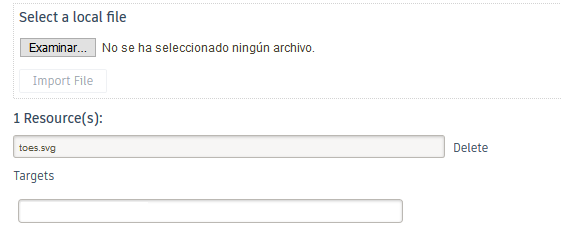
For some unknown reason, TinkerCAD does not recognize the proper units by default. For that reason, we need to change the recently imported file (on the left menu within the “resources” tab) and replace width=”66mm” and height=”25mm” with width=”66px” and height=”25px”, respectively.
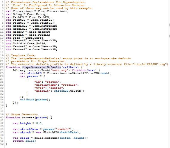
Now, in the “main.js” file, we can assign the geometry we have just imported by replacing the name ‘circle-2RL4RC.svg’ with ‘toes.svg’ inside the function “shapeGeneratorDefaults” and the line “var height = 20.0;” with “var height = 3.0;” within the “process” function. Save the changes to take effect.
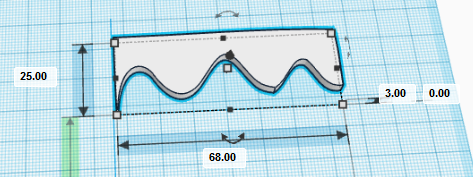
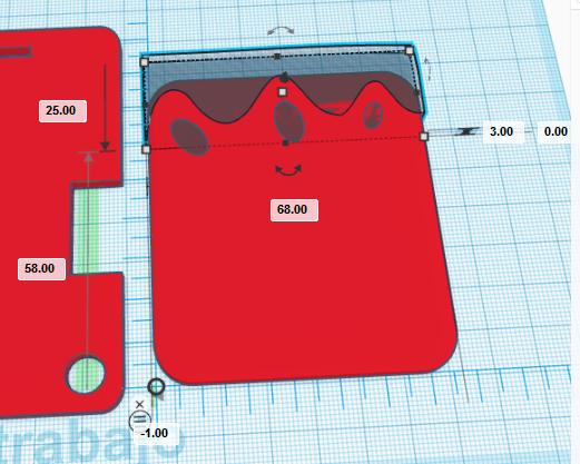
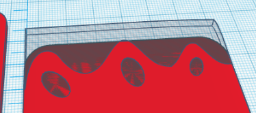
After all this process, we should have the following shape (we have fit the size to 68x25x3 mm, slightly larger than the original shape so that we make sure that the borders are completely removed):
Now, we can place the new shape just in front of the foot, at coordinate (-1,58,0) mm and convert it to a hole shape. We can also create three cylinders of height 3mm with an arbitrary shape as if they were nails of the toes with arbitrary orientation.
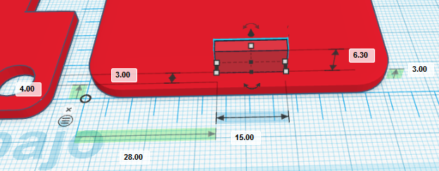
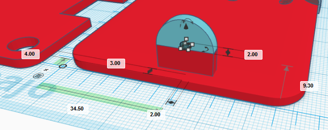
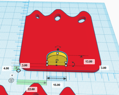
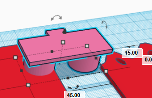
In order to create the ankle, we will create a cube of dimensions (15,3,6.3) mm and place it in the coordinate (28,4,3) mm.
Then, we will create a round roof with dimensions (15,3,7.5) mm, place it in the coordinate (28,4,9.3) mm.
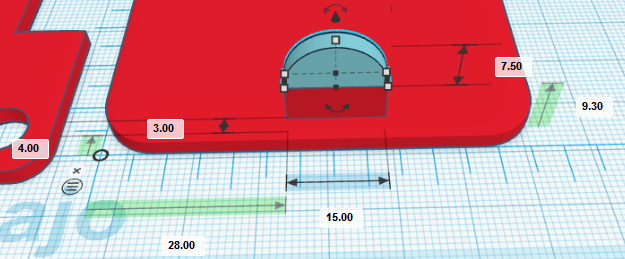
Finally, we will need to create a hole for the rivet. The diameter is 2mm so that the dimensions of the cylinder will be (2,2,3) mm and we will need to rotate it with respect to X-axis 90º degrees.
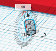
Place the cylinder at coordinate (34.5,4,9.3) mm
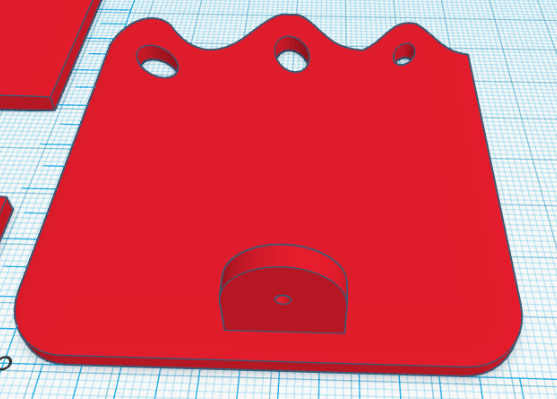
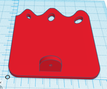
Now, group all foot-related shapes and we’ve got it!
To create the right foot, we will copy the left foot and place it on top-right corner of the workplane. We will move the ruler and make sure the foot is placed at coordinate (0,0,0) mm with respect to the new position of the ruler.
Now, we need to ungroup the geometries corresponding to the right foot and regroup them so that the objects corresponding to the foot sole and toes are all grouped together and the ankle (with the hole) is another group. We have assigned two different colours to each group.
Now, we need to rotate 180º with respect to the Y-axis (mirror it) and move the ankle to the new coordinates (22.6,4,3) mm.
Finally, we will group the objects together so we have the right foot.
Legs Design
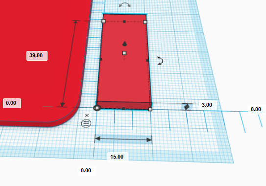
The design for the legs is the same for both legs. We will describe the design process for one of them (let’s say left leg). We need to move the rule to the right of the left foot and create a cube with dimensions (15,39,3) mm placed at coordinate (0,0,0) mm with respect to the ruler.
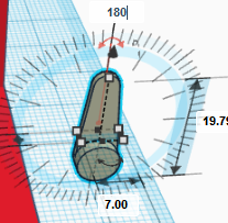
Now, we can import the STL file “servo_horn.stl” and make it hole shaped. Rotate it 180º and placed it at coordinate (4,16,0) mm, as shown.
Repeat the process again, but now, the horn will be pointing downwards, which means that we need to rotate it 180º with respect to the existing one and place it at coordinate (4,3.21,0) mm.
If we group objects, we should have the following result:
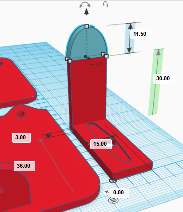
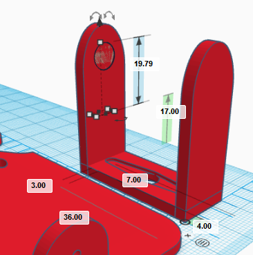
Now, let’s create the front side of the leg. So we need to create a cube of dimensions (15,3,30) mm and place it at coordinate (0,36,0) mm.
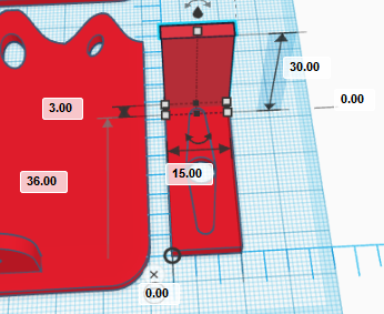
In order to have a rounded shape, we need to create a curved roof with dimensions (15,3,11.5) mm and position (0,36,30) mm.
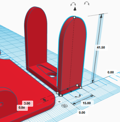
Group the parts corresponding to the front-side leg
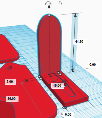
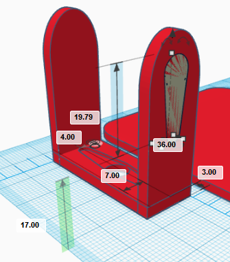
and copy and paste it to create the rear-side part and place it at coordinate (0,0,0) mm.
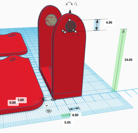
Now, we import again the STL file “servo_horn.stl” and rotate it 90º with respect to X-axis, and 180º with respect to Y-axis as shown in next figures:
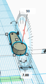
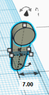
Once rotated, we can place it at coordinate (4,36,17) mm and make it hole.
In order to create the hole for the ball bearing, we need to create a cylinder rotated 90º with respect to the X-axis and dimensions (4.9,3,4.9) mm (once rotated). Place it at coordinate (5.05,0,34.05) mm
In order to complete the leg, we will simply group all objects
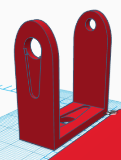
As mentioned before, the right leg is the same so we just simply need to copy and paste it at a different position (to the right of the right foot).
Face Design
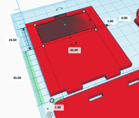
To create the robot’s face, we will move the ruler to the top-left corner of the workplane. We start by creating a cue of dimensions (60,70,3) mm and positioning it at coordinate (0,0,0) mm.
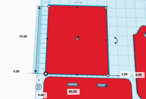
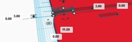
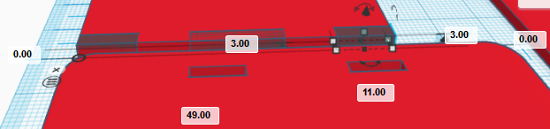
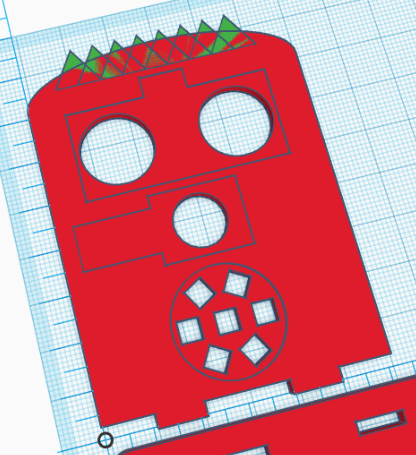
Now, we will create three hole cubes with dimensions (11,3,3), (18,3,3) and (11,3,3) mm placed at coordinates (0,0,0), (21,0,0), y (49,0,0) mm, respectively. Group them to create the geometry shown:
Now, we need to import the file “HC-SR04.stl” and rotate it 180º with respect to the X-axis as shown.
Make the object hole and place it at coordinate (7.5,45,3) mm.
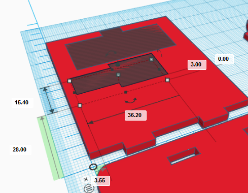
Repeat this process with the buzzer file, rotate it 180º with respect to the X-axis, make it hole and place it at (3.55,28,3) mm.
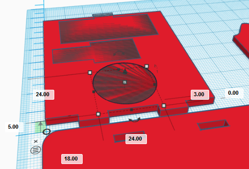
For the LEDs strip (robot’s mouth), we will need to import the file “LED_round_strip_ws8212.stl” and repeat the process of rotating the object 180º with respect to the X-axis, make it hole and place it at coordinate (18,5,3) mm.
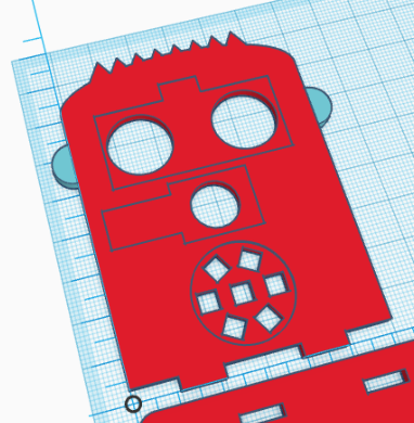
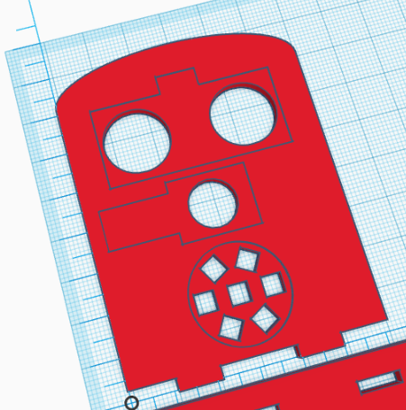
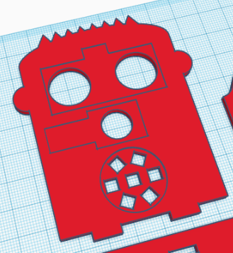
In order to add some fancy decorations, we can create some hair, following a similar process used to create the toes or simple que can make the front face rounded as shown.
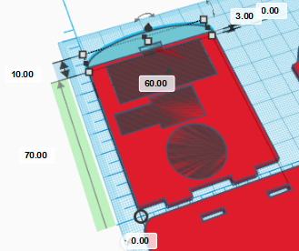
Here we also show some ideas…
With all parts created, now you are in position of 3D Printing them.