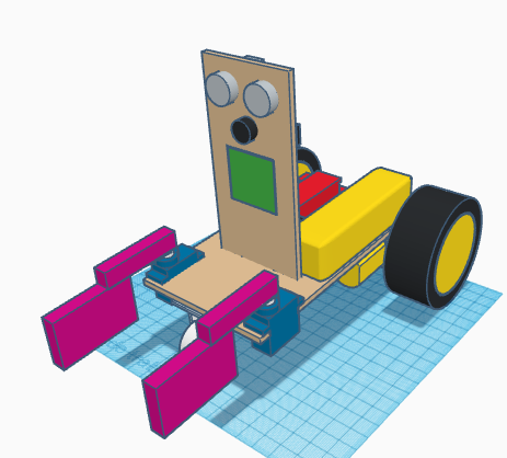
In this entry, we show the assembly of DYOR DIY Standard with TinkerCAD and make with laser cutting.
Components:
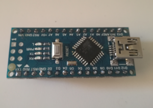
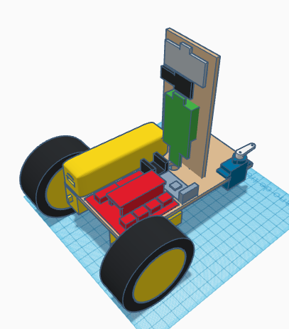
- Arduino Nano + Shield Arduino Nano I/O (red)
- Powerbank (yellow)
- Ultrasound HC-SR04 (light grey)
- Buzzer (black)
- Servos SG90 ( blue) in the base
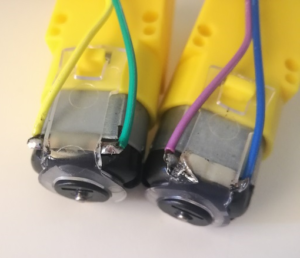
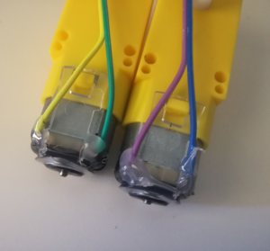
- SmartCar motors (yellow)
- SmartCar wheels (yellow/black)
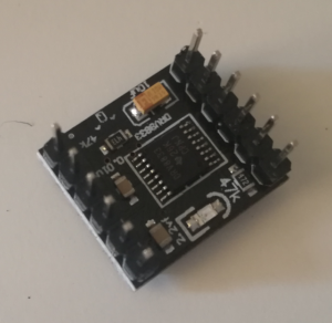
- Driver DRV8833 (black)
- Bluetooth (grey)
- Linetracker TCRT5000 (dark blue)
- Caster wheel (white)
- FS90R wheels (black)
- LED Matrix (green)
- LEGO parts (magenta)
Instructions:
Soldering
In order to assemble this robot, we will need to solder some pins. It is convenient to have all this ready for assembly, so run the soldering steps first (after reading all assembly instructions).
The DRV8833 motor driver requires some pins to be soldered, as shown in Figure:

Similarly, Arduino Nano v3.0 also requires pins soldering, as shown in Figure:
Finally, SmartCar motor comes without cables, but some terminal connector instead. We recommend using DuPont Cables to create proper cable connections. So cut one of the ends of the cables and peel it out and twist it around the motor terminal. To avoid soldering get damaged, we recommend to glue the cable, once is soldered.
DYOR DIY Component soldering video:
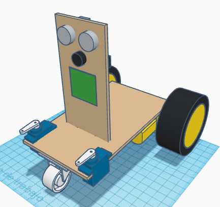
Assembly
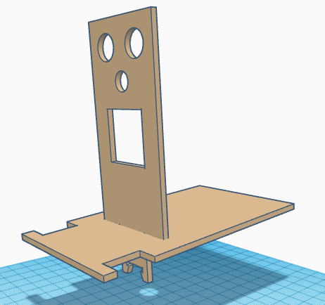
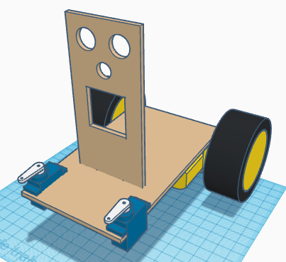
Glue both parts, the base and the frontal face.
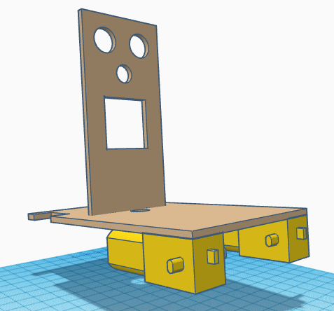
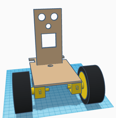
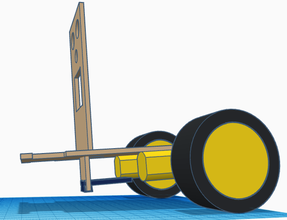
Glue SmartCar motors to the base, with the axis as rear as possible. Fix the SmartCar wheels to the motor axis.
Glue the TCRT5000 sensor at the bottom part of the front trying to place it as far as possible to the front, to avoid collision with the cast wheel (later).
Glue the SG90 servos with the axis as close as possible to the front. Screw the servo horns so that the mid position of 90º is as shown.
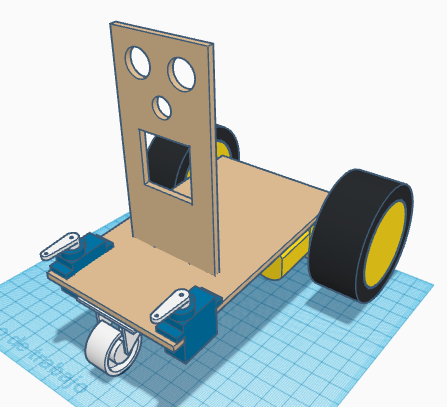
Glue the caster wheel below the base at the front part. Make sure that it freely turns and it is centred.
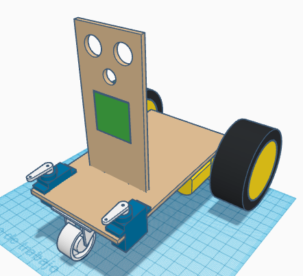
Pass the cables of servos and TCRT5000 through the hole at the base. Glue the LEDs matrix with the input connector pointing downwards.
Glue the buzzer.
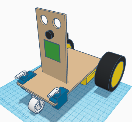
Glue the ultrasound sensor HC-SR04 with the connector pointing upwards.
Glue the Arduino electronics, Powerbank, DRV8833 driver and Bluetooth module to the robot base.
Finally, glue the LEGO parts corresponding to the grip to the servo SG90 horns.