In this entry, we show the assembly of DYOR qPED in TinkerCAD for laser cutting manufacturing.
Components:
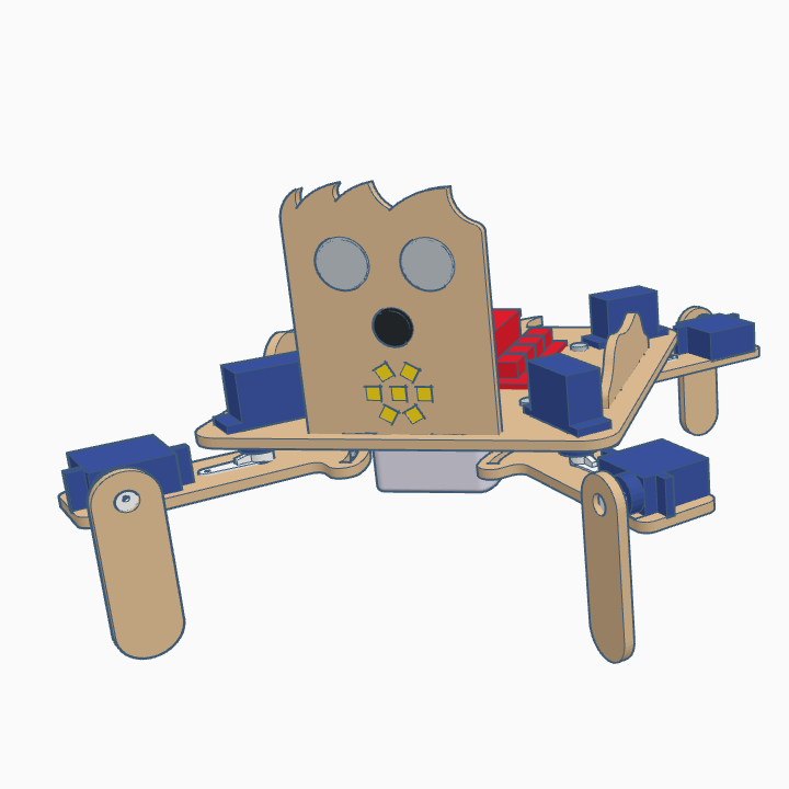
- Arduino Nano + Shield Arduino Nano I/O (red)
- Powerbank (white)
- Ultrasound HC-SR04 (light gray)
- Buzzer (black)
- Servo SG90 (dark blue)
- Rounded LED strip (yellow)
- Bluetooth (dark blue)
Instructions
Make sure that the servos at positioned at 90º before you screw the servo horns to the axis. The robot has four legs, with two parts par each leg that will be denoted as “leg part” the one being in contact to the ground and “hip part” as the one joining the robot base and the “leg part”.
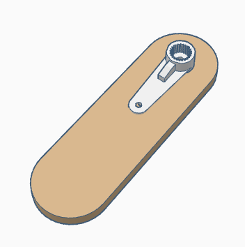
Before starting, glue the servo horns to the “hip parts” and “leg parts”
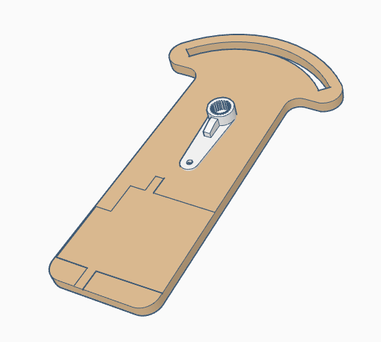
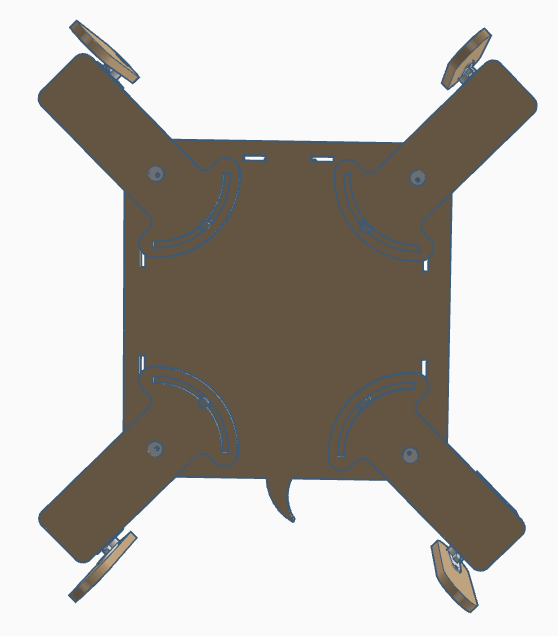
Glue servo legs to each of the “hip parts”. Take into account the line engraving of each part to properly place the servos. The are two possible configurations for the left and right, so pay attention. The assembly of the front and rear legs are identical, so we will only show the assembly of the front ones.
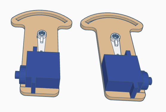
Screw the servo horns of the “leg parts” to the servos that have just been glued to the “hip parts”. Make sure that the configuration of the legs is as shown, since this will be considered as the home configuration.

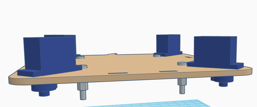
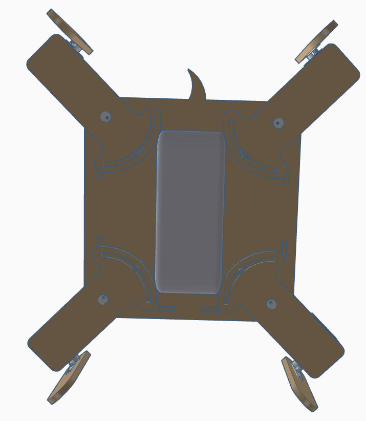
Glue the four servos of the hips to the robot base, with the axis pointing downwards and as close as possible to the corner.
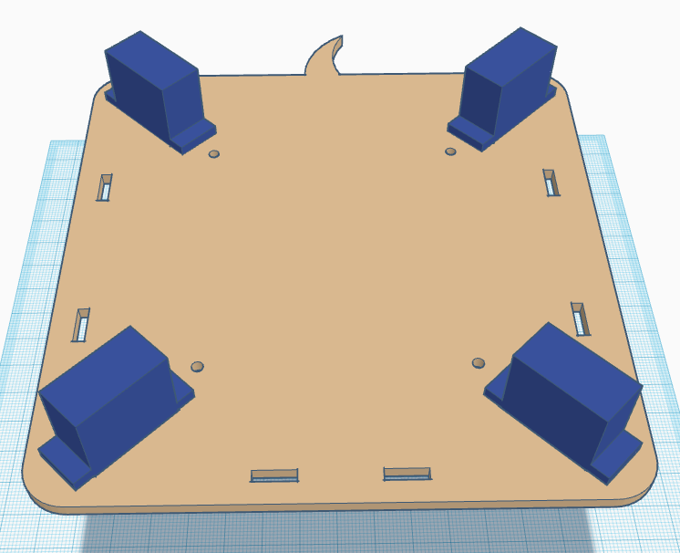

Screw the M3 screws to the M3 spacers through the round holes at the robot base.
Now, from the bottom side, we must screw the servo horns to the hip servos with the “male” connector of the M3 spacer passing through the corresponding hole of the “hip part”. Take into account that the robot’s legs are always at the inner side of the legs.
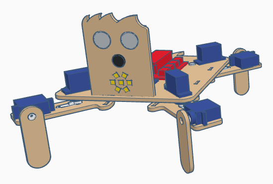
Now, glue the Arduino electronics and the bluetooth module on the robot’s base.
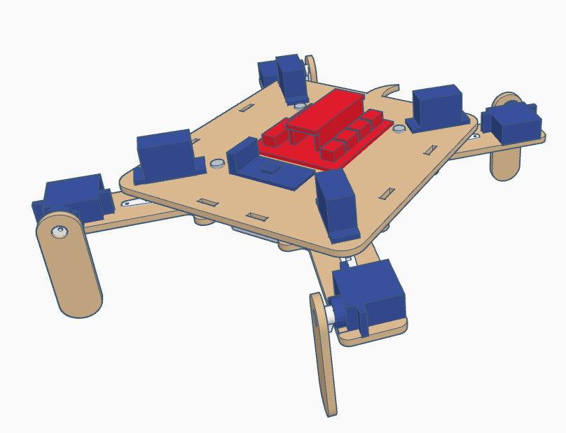
Also, glue the robot’s face.
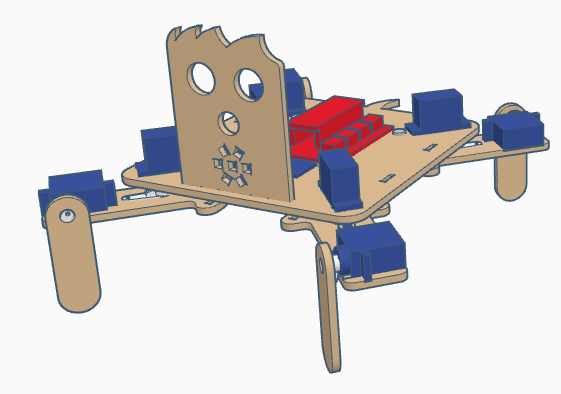
And the rounded LED strip to it (it requires to solder the cables to the pins first).
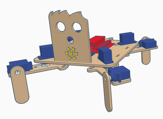
After that, we can glue the buzzer
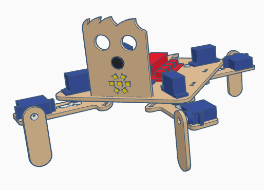
and the ultrasound snesor with the pins pointing upwards.
Again, in the bottom side we must glue the powerbank. The space withing the “hip parts” is narrow, but it should fit inside (make sure that it does not collide with any “hip part”).
Finally, we will add the decorative elements on the sides.