The purpose of this entry is to describe necessary steps to design a servo with QCAD, as SG90 or TS90M servos used in the gripper.
Our aim is to design a CAD model of a servo, SG90 or TS90M, used in the robot’s gripper. The servo axis is pointing upwards and supported by the robot’s base, so they need a hole to fit in. For that reason, we will use the cut layer for the hole of the servo body, engraving layer to draw the servo ears and the reminder of elements will be drawn in the auxiliary layer.
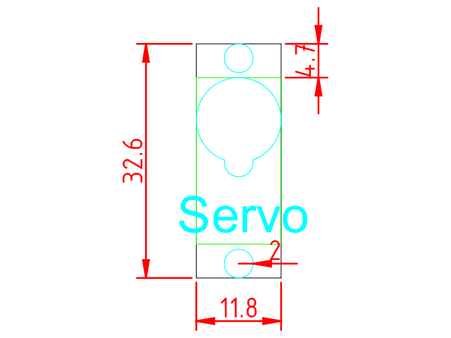
The servo measurements are shown below:
Here you can find the template used:
Select the engraving layer and create a polyline with the following commands to draw the ears of the servo:
polyline
0,4.7
@0,-4.7
@11.8,0
@0.4.7
polyline
0,27.9
@0,4.7
@11.8,0
@0.-4.7
Then, selecting the cutting layer, we can create the hole for the body:
polyline
0,4.7
@11.8,0
@0,23.2
@-11.8,0
@0,-23.2
Now, in the auxiliary layer we can create two holes representing the gears and holes for screws. First, let’s draw the circles for the holes for the screws:
circle
5.9,30.6
2
circle
5.9,2
2
Then, we need other two circles to draw the gears:
circle
5.9,22
5.9
circle
5.9,16.1
2
Now, you can introduce the command “arrc” and select as centre the point 5.9,22, a point belonging to the circle of radius 5.9 and as initial and final angles the points where it intersects with the other circle. Once the arc has been created, you can delete the original circle. Repeat this process to create the other arc. You can use the tool to create a polyline from segments to join them all together as the same object. Finally, you can write a text and add dimmensions too.
Here, you can download the solution: