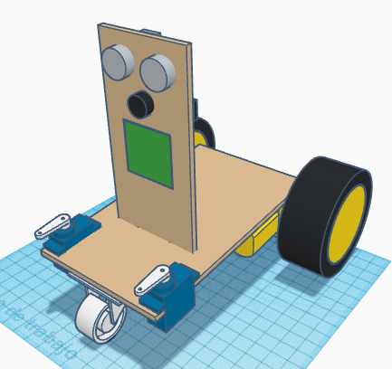
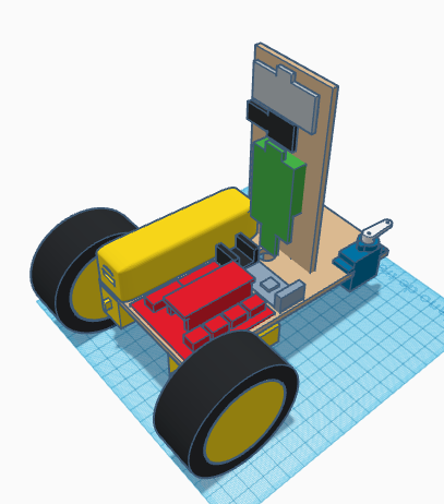
[:es]En esta entrada os mostramos el ensamblaje del robot DYOR DIY Standard realizado con TinkerCAD y fabricado con corte láser.
Componentes:
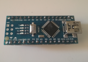
- Arduino Nano + Shield Arduino Nano I/O (rojo)
- Powerbank (amarillo)
- Ultrasonido HC-SR04 (gris claro)
- Zumbador de sonido (negro)
- Servos SG90 (azul) en la base
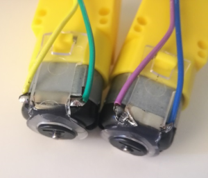
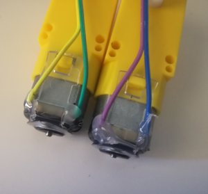
- Motores SmartCar (amarillo)
- Ruedas SmartCar (amarillo/negro)
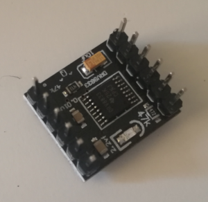
- Driver DRV8833 (negro)
- Bluetooth (gris)
- Seguilíneas TCRT5000 (azul oscuro)
- Rueda loca (blanco)
- Matriz de LEDs (verde)
- Piezas de LEGO (morado)
Instrucciones:
Soldadura
Para el montaje de este robot necesitaremos soldar algunos pines y cables. Es conveniente tener preparado previamente todos los componentes antes de pegarlos y por tanto, se recomienda realizar los pasos de soldadura al principio de todo (leer todas los pasos de las instrucciones previamente).
Los pines de driver DRV8833 requieren ser soldados, tal y como se muestra la figura:

Similarmente, los pines del Arduino Nano v3.0 requieren ser soldados, tal y como se muestra en la figura:
Finalmente, los cables de los motores SmartCar requieren también soldadura. Para ello, soldaremos unos cables DuPont a los motores en los terminales metálicos que tiene (debemos cortar uno de los extremos del cable y pelarlo adecuadamente y enrollarlo al terminal del motor). Para evitar que la soldadura se dañe, es conveniente añadir un poco de pegamento una vez soldados.
Vídeo explicativo al respecto de la soldadura de los componentes:
Ensamblaje
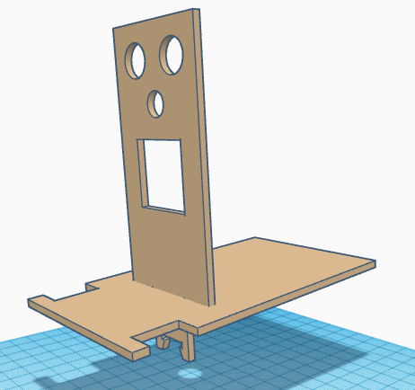
Colocar la pieza del frontal junto con la base y pegarlas.
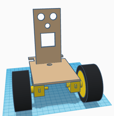
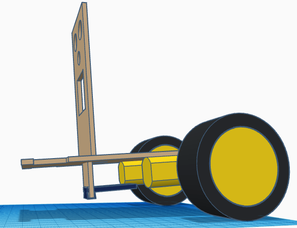
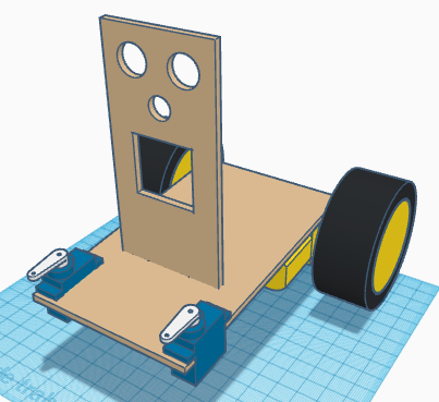
Pegar los SmartCar a la base, estando el eje lo más atrás posible y acoplar las ruedas SmartCar.
Pegar el sensor TCRT5000 en la parte inferior del frontal, procurando que sobresalga lo menos posible para que no colisione con la rueda luega que posteriormente pegaremos.
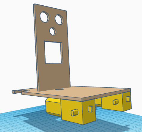
Pegar los servos SG90 estando el eje lo más adelantado posible. Atornillar la manilla del servo de forma que esté, tal y como se muestra en la figura, en su posición intermedia de 90º.
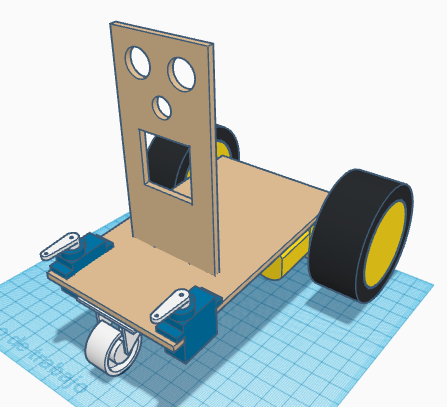
Pegar la rueda loca en la parte delantera de la base. Asegurarse que la rueda tiene el giro libre y que está centrada.
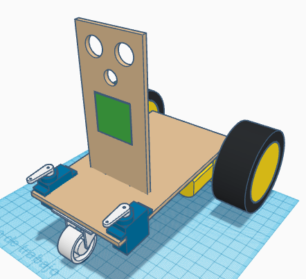
Pasar los cables de los servos FS90R y SG90, así como los cables del sensor TCRT5000 por el orificio de la base. Pegar la matriz de LEDs con los conectores de entrada en la parte inferior.
Pegar el zumbador.
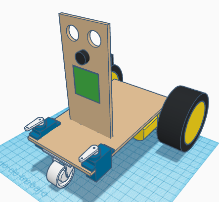
Pegar el ultrasonido HC-SR04 con el conector apuntando hacia arriba.
Pegar el powerbank, la placa de expansión Arduino Nano I/O, el driver DRV8833 y el módulo bluetooth en la base del robot.
Pegar las piezas LEGO que sirven de pinza a las manillas de los servos SG90.
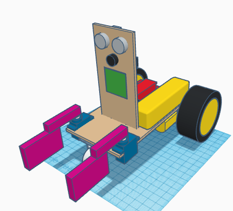 [:en]In this entry, we show the assembly of DYOR DIY Standard with TinkerCAD and make with laser cutting.
Components:
- Arduino Nano + Shield Arduino Nano I/O (red)
- Powerbank (yellow)
- Ultrasound HC-SR04 (light grey)
- Buzzer (black)
- Servos SG90 ( blue) in the base
- SmartCar motors (yellow)
- SmartCar wheels (yellow/black)
- Driver DRV8833 (black)
- Bluetooth (grey)
- Linetracker TCRT5000 (dark blue)
- Caster wheel (white)
- FS90R wheels (black)
- LED Matrix (green)
- LEGO parts (magenta)
Instructions:
Soldering
In order to assemble this robot, we will need to solder some pins. It is convenient to have all this ready for assembly, so run the soldering steps first (after reading all assembly instructions).
The DRV8833 motor driver requires some pins to be soldered, as shown in Figure:
Similarly, Arduino Nano v3.0 also requires pins soldering, as shown in Figure:
Finally, SmartCar motor comes without cables, but some terminal connector instead. We recommend using DuPont Cables to create proper cable connections. So cut one of the ends of the cables and peel it out and twist it around the motor terminal. To avoid soldering get damaged, we recommend to glue the cable, once is soldered.
DYOR DIY Component soldering video:
Assembly
Glue both parts, the base and the frontal face.
Glue SmartCar motors to the base, with the axis as rear as possible. Fix the SmartCar wheels to the motor axis.
Glue the TCRT5000 sensor at the bottom part of the front trying to place it as far as possible to the front, to avoid collision with the cast wheel (later).
Glue the SG90 servos with the axis as close as possible to the front. Screw the servo horns so that the mid position of 90º is as shown.
Glue the caster wheel below the base at the front part. Make sure that it freely turns and it is centred.
Pass the cables of servos and TCRT5000 through the hole at the base. Glue the LEDs matrix with the input connector pointing downwards.
Glue the buzzer.
Glue the ultrasound sensor HC-SR04 with the connector pointing upwards.
Glue the Arduino electronics, Powerbank, DRV8833 driver and Bluetooth module to the robot base.
Finally, glue the LEGO parts corresponding to the grip to the servo SG90 horns.
[:]