Stuart can follow lines, avoid obstacles and is controlled via iOS app.
The task generally consisted of 4 parts.
- Design of the robot
- Assembly of the robot
- Implementation of two autonomous programs
- Implementation of a remote control via Bluetooth
Design of the robot
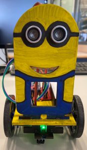
The first step was to find a design. I decided to use an existing kit of a Minion and let it drive with two wheels and a caster wheel. The kit is made from 3mm thick wood and is manufactured by laser cutting.
The next step was to provide a 3D robot assembly in SolidWorks to visualize our idea. The sketches for most of the parts were provided so that they had to be extruded and assembled to a robot.


Assembly of the robot
Once the design has been defined and visualized, the next step is to procure the individual components. The following list shows the components used here.
- 1x Robot kit Minion
- 2x Motors (fs90r)
- 2x Wheels (rueda-fs90r)
- 1x Caster wheel
- 1x Arduino Nano 3
- 1x Arduino Nano IO Extension Shield
- 1x Powerbank 3600 mAh
- 1x Cable Mini USB
- 2x Cables Dupont (10 pieces)
- 1x Ultrasonic Sensor hc-sr04
- 1x Infrared Sensor tcrt5000
- 1x Bluetooth Low Energy (BLE) -> Important to use a BLE if you want to connect it with an iOS device
It is recommended to first paint the parts and later assemble them. Like this you have an easier access. Acrylic paint is a cheap and easy choice to paint the parts.
For gluing, a superglue worked perfectly, but you have to be quick. With a pencil you can sketch first the edges of the electrical components on the wood. This will facilitate and accelerate the positioning.
With the Dupon cables the electronics can now be connected. Most of them have three connections. Ground (G), voltage (V) and signal (S). They have to be connected accordingly on the Arduino extension shield pins. Nevertheless, there are some limitations
- PIN 0 & 1: Even if these are marked with RX and TX, they should only be used for USB connection. DO NOT use them to connect the Bluetooth module.
- PIN 2 – 13 can all be used as digital in- & outputs. Notice that via PIN 13 the integrated LED on the Arduino Nano can be controlled.
- PIN A0 – A5 can be used as analog inputs and as digital in- & outputs.
- PIN A6 & A7 are only analog inputs.
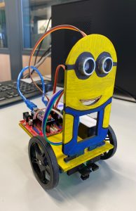
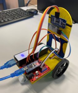
The finished assembled robot looks like this.
Implementation of two autonomous programs
Obstacle avoidance
The program consists of a loop and starts with a command to let the robot drive forwards. Every 0.1 seconds he measures with the ultrasonic sensors the distance to the next object ahead. If the measured distance is smaller than a predefined threshold distance, the robot drives backwards, turns randomly, and drives forwards again. If there is no obstacle within the threshold distance, the robot keeps driving forwards.
The implemented program flow chart and the Arduino code is as following.

Here the Servos are connected to the pins 6 and 9 and the ultrasonic sensor to pin 11 and 12. Moreover the driving forwards movement is already calibrated.

Line following
For the line following algorithm the corresponding block from Facilino can be used. It is important that black and white are defined correctly. To do this, connect the robot to a computer via USB cable. In the setup you have to write Serial.begin(9600); and in the loop Serial.println(analogRead(A0)); (assuming that you have connected the infrared sensor to pin A0). Now you can read the value from the sensor in the menu under “Tools”->”Serial Monitor”.
Implementation of a remote control via Bluetooth

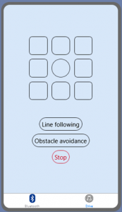
A detailed description and explanation of the code and the structure of the app is omitted here, because it is described very well on the Youtube channel of Leopoldo Armesto (e.g. https://www.youtube.com/watch?v=T_pnt3jIrLo).
However, it is important that the Bluetooth command is sent as a char and not as a string. The command “0” ends any activity by default.
It should be noted that compared to remotely controlling the robot, the line following and obstacle avoidance algorithms are loops and not one-time commands. Therefore, here the command must be stored in the variable “_bt_cmd” so that the algorithm is executed in every iteration.
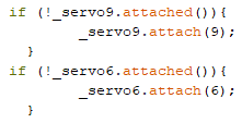
Another aspect to consider is that the timer from the Bluetooth module interferes with the servos unintentionally. Even if the servos do not receive a command, they perform slow jerky movements. To avoid this problem, it is advisable to detach the servos in the setup and then always attach and detach them again.
You can detach them by following command
![]()
and attach them to pin 9 and 6 by this command.