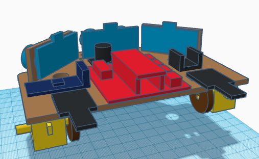
In this entry we show the assembly of DYOR Pro robot with TinkerCAD and manufactured with laser cutting.
Components:
- Arduino Nano + Shield Arduino Nano I/O (red)
- Powerbank (orange)
- Ultrasound HC-SR04 (light blue)
- Buzzer (black)
- SG90 Servo (dark blue) en la pinza
- SmartCar Motor (yellow) en la base
- Bluetooth module (dark blue)
- TCRT5000 linetracker (dark blue)
- Ball wheel (white)
- SmartCar Motor Wheels (black/yellow)
- LEDs Matrix (green)
- SmartCar Encoder discs (brown)
- HC-020k Encoders (black)
- Round 7-LEDs strip (gray)
- MR52ZZ ball-bearing, screw and nut.
Instructions
Before assemblying this robot, we will need soldering of some pins. It is convinient to handle all this before assembly.
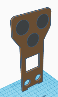
The round 7-LEDs strip needs soldering of input and output pins. We can simply use DuPont cables for this purpose. For instance, we can leave the female connector and cut the other end of it and solder it to the input connector of the left eye (on the back side corresponds to the Round 7-LEDs strip on the right). The connections between the left eye and the right eye must be also done by soldring some short cables from one to the other. Finally the connections from the right eye and the mouth will be also done by soldering some short cables among them. In summary, the LEDs strip must start by connecting the left eye (through its input connection), then the right eye and finally the mouth. Please, respect that order if you intend to use Facilino’s instructions.
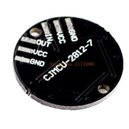
Soldering is relatively easy. We simply need to connect the pins with VCC and GND from one board to the corresponding ones of the next board. The OUT pin of the left eye will be connected to the IN pin of the right eye. Also the OUT pin of the right eye will be connected to the IN pin of the mouth. The OUT pin of the mouth is unconnected.
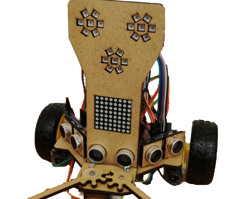
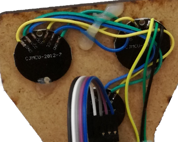
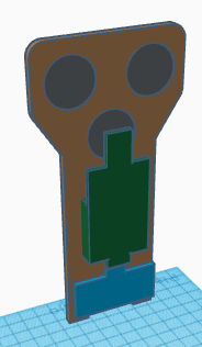
Once everything is soldered, then we can glue them to the robot’s face.
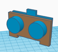
Here we show an example of how it should be done:
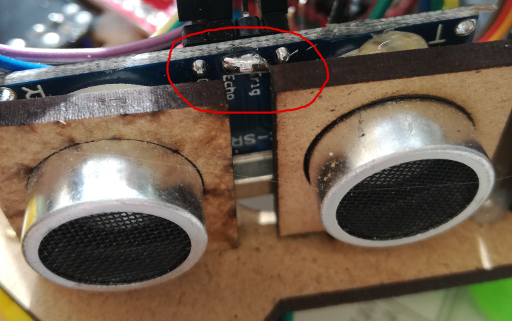
Ultrasonic sensors, need to be “hacked” so that with one single line we can trigger and receive the echo. So the pins ECHO and TRIG must be short-circuited as shown:
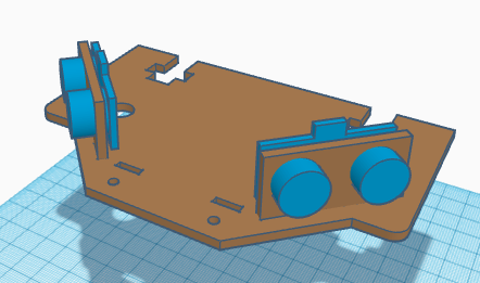
Once done, we are in conditions of glueing them to their corresponding supports for the ones on the sides or to their corresponding holes in the robot’s face.
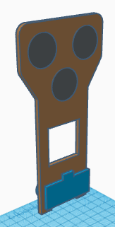
Connect the cables of the ultrasound sensors before glueing the LEDs matrix. The cables of the LEDs matrix will be connected from the top side.
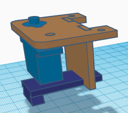
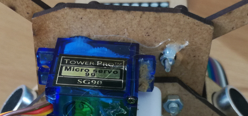
Assembly of the robot’s grip requires to glue the SG90 servo on the corresponding hole. Please, note that to make the fingers co-plannar, only the rounded shape around the servo axis will be fitted on the hole, so that the finger is mostly in contact with the gripper surface. The sensor TCRT5000 is glued using its corresponding support, placing it as close as possible to the servo and with the potentiometer on the front-side of the support to avoid collisioning with the ball-wheel we will lately use.
The right finger must be screwed to the servo’s axis (no servo horn is required) and if it necessary, we can glue the screw to the finger. The small hole on the grip if for the ball bearing MR52ZZ, so it must be fitted inside. Then, we can simply use the screw and the nut to fit the left finger through the ball bearing. It is usually convinient to glue the nut to the grip to make sure that the finger does not fall apart.
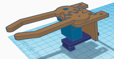
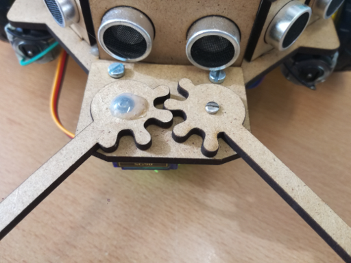
Please, note that the picture above does not exactly correspond to the same grip design, but the principle is the same.
Now, we can glue the ultrasound sensors, with their supports on the robot’s base sides.
Also the pins of the DRV8833 require soldering, but this is quite straight-forward, as shown in next figure:

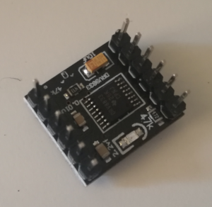
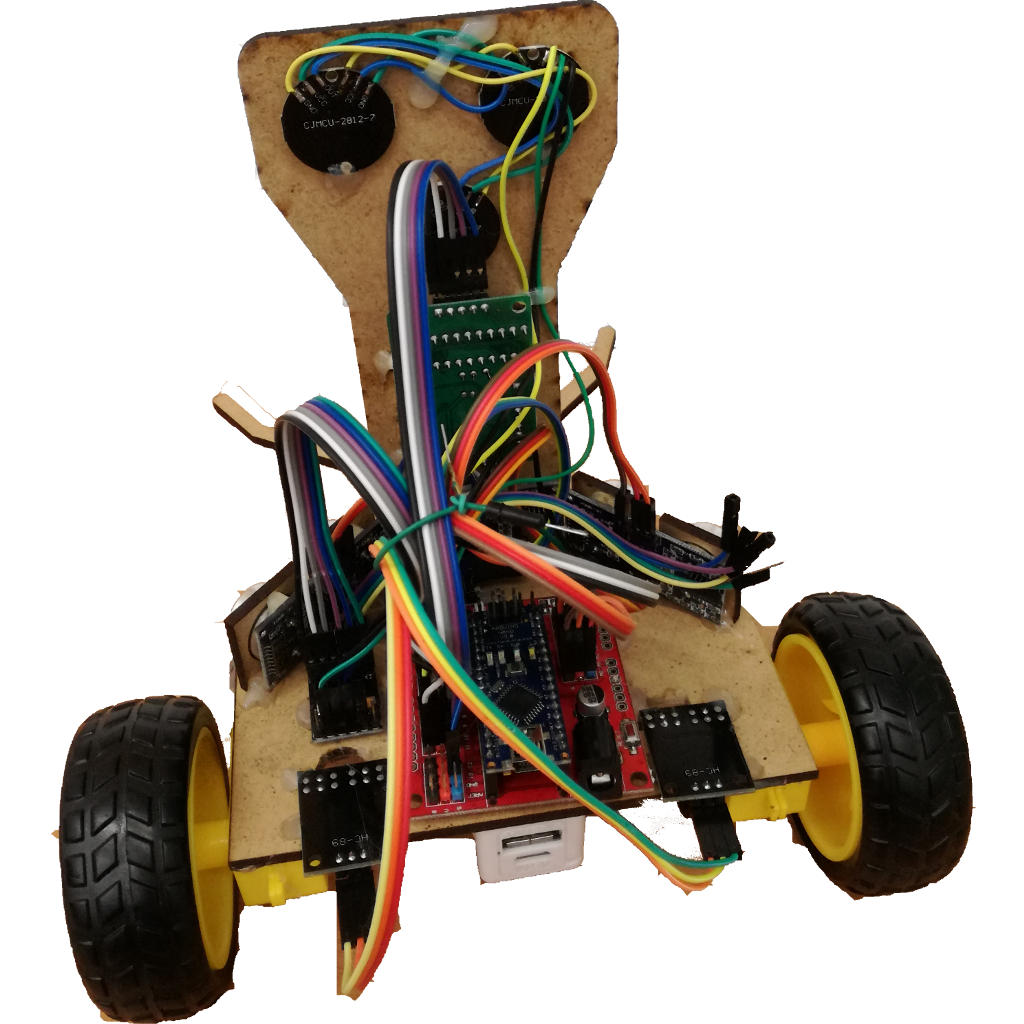
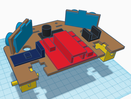
Once complete, we can glue the buzzer, the DRV8833 driver, the bluetooth module and the Arduino Nano expansion shield to the robot base.

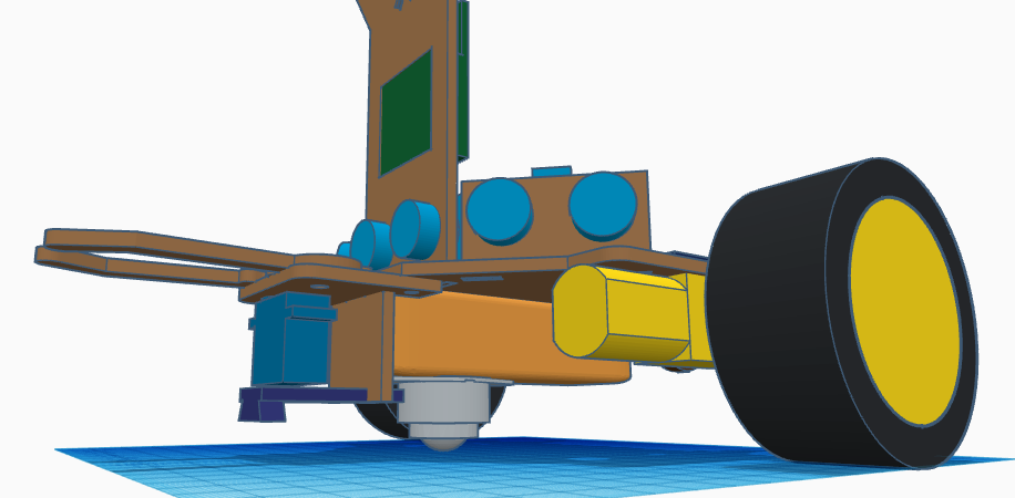
Now, we can glue the motors to the robot’s base at the bottom of it. We also need to solder some cables to the motor electric terminals (it is convinient to use some glue after the pins have been soldered, because they can easily get disconnected with the cable is pulled).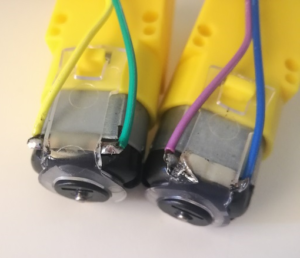
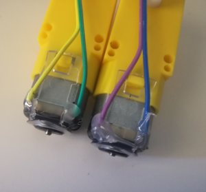
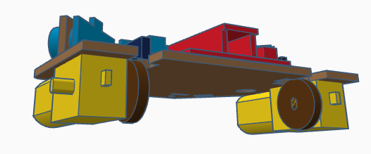
Glueing the motors at the botoom of the base is quite easy, with the only consideration that the motor axis must be as rear as possible and as close as possible to the robot sides.
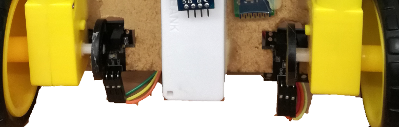
Once glued, we can put the encoder discs on the axis. Make sure that they are as centred as possible with respect to the hole on the base corresponding to the HC-020k sensors.
Now, place the HC-020k sensors as shown and make sure that the disc is correctly placed in the middle of the sensor.
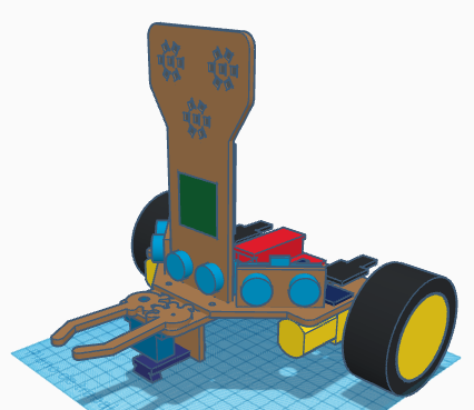
Fix the robot wheels

Screw the gripper to the robot’s base.

and glue the robot’s face to the base
Pass all cables corresponding to the SG90 servo, TCRT5000 sensor, and motors through the holes. After that, we can glue the powerbank to the bottom side of the base (as close as possible to the TCRT5000 support). Glue the ball wheel at the bottom of the powerbank.