Learn how to use a 8×8 LEDs matrix (max7219). DYOR robot has a LEDs matrix to generate expressions (as a mouth). We describe it’s working principle and examples of use with de uso con Facilino and Arduino.
How does a LEDs matrix work?
As in a mobile phone or computer screen composed by pixels, the 8×8 LEDs Matrix has upto 64 red LEDs which we can use to draw almost anything, actually, we have 18446744073709551616 combinations!
The LEDs module communicates through SPI (Serial Programming Interface) with Arduino. It’s a communicaton protocol very common between microcontrolers and devices, with bidirectional communication which requires upto 4 lines (one for loading data, another one for the clock, one for data input and one for data output). However, given that the communication between Arduino and the LEDs module it’s unidirectional, we only require 3 lines: signals CS (Chip select), also known as LOAD, allows us to enable the device to receive information; signal DIN es the data input signal (to the module) and signal CLK is the clock signal.

Arduino Nano has SPI signals that can be used for this purpose:
- MISO (Master In Slave Out) – The Slave line for sending data to the master, assigned to pin 12
- MOSI (Master Out Slave In) – The Master line for sending data to the peripherals assigned to pin 11
- SCK (Serial Clock) – The clock pulses which synchronize data transmission generated by the master, assigned to pin 13
- SS (Slave Select) – Assigned to pin 10
The matrix orientation of DYOR’s robot LED matrix (standard robot) is shown in next figure:
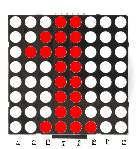
In order to activate pins, we must think of sending a value to the hole row, actually a column in previous figure due to it’s orientation. Therefore, in order to generate the previous drawing, we must send the following numbers for each row starting with it’s binary combination with the LSB (Least Significant Bit) the ones on the top:
F1=0
F2=2^2=4
F3=2^1+2^2+2^7=134
F4=2^0+2^1+2^2+2^3+2^4+2^5+2^6+2^7=255
F5=2^0+2^1+2^2+2^3+2^4+2^5+2^6+2^7=255
F6=2^7=128
F7=0
F8=0
How is it connected?
For this particular module, we need three signals to communicate with the device, in addition to the power and ground signals. We can connect them to any digital pin of Arduino, but it’s better if we connect them to SPI signals:
- VCC: Power. Connect to any +5V pin.
- GND: Ground. Connect to any 0V pin.
- CS: Digital output. Connect to any digital pin of Arduino.
- DIN: Digital intput. Connect to any digital pin of Arduino.
- CLK: Digital output. Connect to any digital pin of Arduino.
Here we show the connection to Arduino Nano v3.0 with the expansion board, where signals CS, DIN and CLK have been connected to pins with dedicated hardware with SPI protocol.
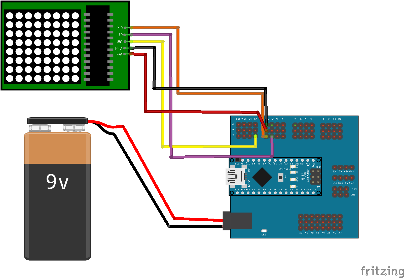
Here you can download the Fritzing diagram:
How to use it?
Programming the LEDs matrix it’s easy. In Facilino, we have one specific instruction for generating predefined expressions for DYOR robot. In addition to this, we can also generate our own instructions in a very intuitive way.
This is an example of Facilino for generating an ‘angry’ expression:

Here you can download the Facilino code:
In this another example, the LEDs matrix is repeatedly generating ‘happy’ and ‘angry expressions:
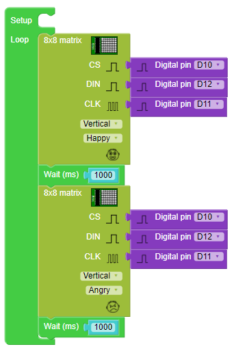
Here you can download Facilino code:
On the other hand, if you are interested in generating different patterns than the predefined expressions, then, we must indicate for each row the LEDs we would like to activate. Internally, the instruction it does take into account the fact that the LEDs matrix can be oriented vertically or horizontally, so we must draw as we would like to appear and select the appropriate module orientation.

Here you can download Facilino code:
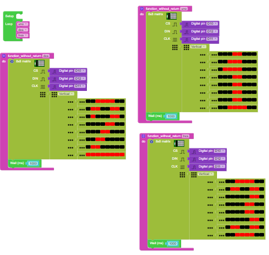
Here we include another example with a countdown from 10 to 0: