In this entry we will explain the necessary steps to customize DYOR robot with TinkerCAD following the example of DYOR BatBot.
We will start with the new design of DYOR robot with arms configuration, as described in Customization of DYOR robot with arms. We need each of individual parts of the robot so we can 3D print them (we have simply removed the engraving layer). We must take into account that the original design has been created for laser cutting, which means that the tolerances for 3D printing are different. This entry is similar to this other entry Customization of DYOR FootBot with TinkerCAD
First download the following design:
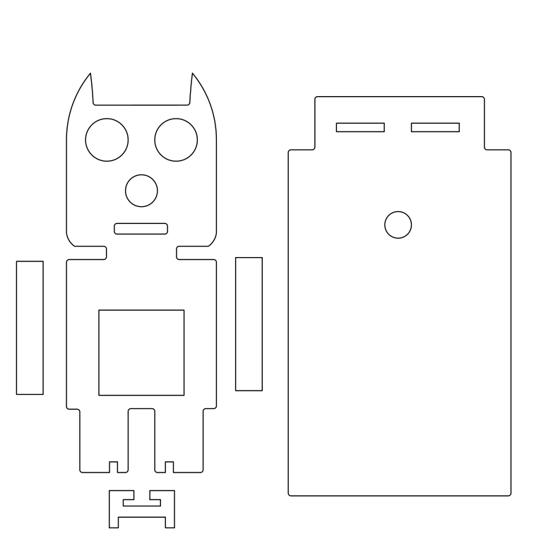
Then, we need to ungroup all objects to create separate files:
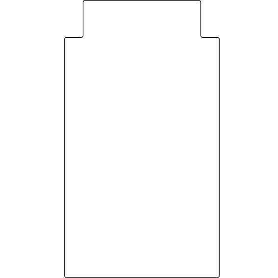
- Head (not including eyes, nose and mouth). Save this file as “batbot_head.svg”

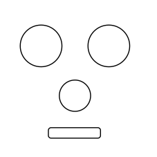
- Face (eyes, nose and mouth). Save this file as “batbot_face.svg”
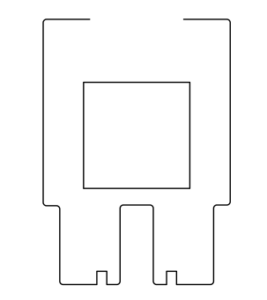
- Body. Save this file as “batbot_body.png”
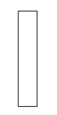
- Arm (for both, left and right). Save this file as “batbot_arm.svg”
- TCRT5000 sensor support. Save this file as “TCRT5000_support.svg”

- Robot base (no holes). Save this file as “batbot_base.svg”
- Base holes. Save this file as “batbot_baseholes.svg”
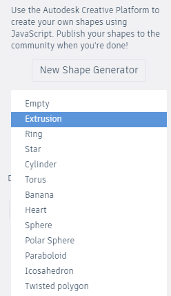
Now, in TinkerCAD, we expand the menu with “Basic Shapes” and select the “Your Shape Generators” and start creating a shape with the button “New Shape Generator” and selecting “Extrusion”

By default, it will be shown a cylinder of 20 mm height, as shown:
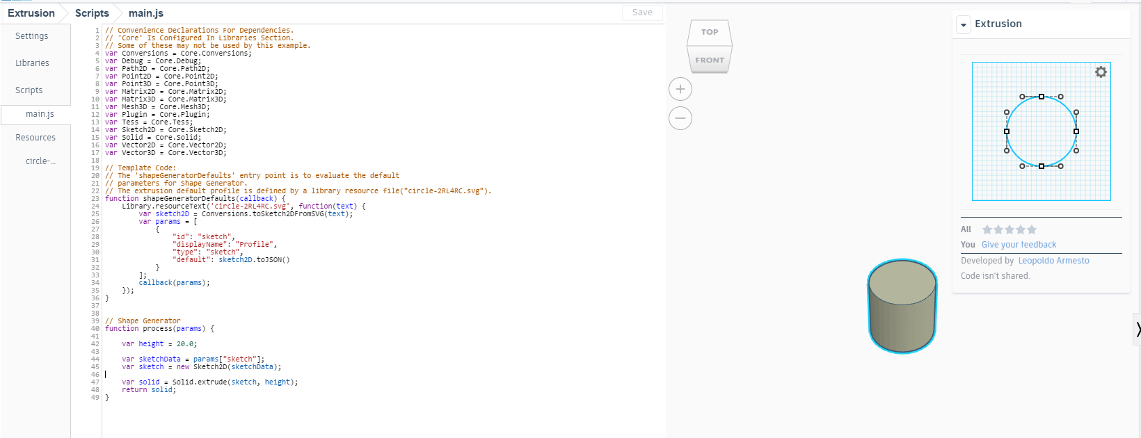
Our aim is to modify the “main.js” so that we will generate our own imported shape. Line 24 contains the name of the file we want to import, so replace it, for instance, with “batbot_face.svg”. In line 42, we will need to modify the height from “20.0” to “3.0”.
In addition to this, in “Resources” tab, we will need to remove the original file and import the corresponding file (name must be the same as before), in this case “batbot_face.svg”. In the “Settings” tab, we can set the shape name and add a description.
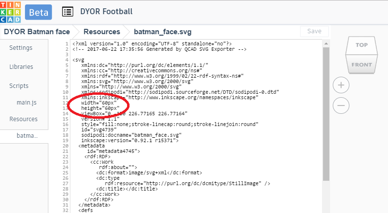
Inkscape generates a “svg” file with a scale depending of the original “dxf” file (by default is in pixels). However, the correct units are not “px”, but “mm”, which means that we have to “undo” this somehow. For that reason, we need to replace this in TinkerCAD, so that the shape generator takes the correct units. We need to open the “svg” file in the shape generator, just below “Resources” tab and modify the units. In our case, lines 12 and 13 have been modified so that “mm” now is “px”.
Once this step is done, we can save the save and this will include a new shape in “Your Shape Generators” with the design in TinkerCAD.
Now, you can customize and modify the proposed design.
As an alternative method, you can directly import the “svg” file in TinkerCAD, however the main difference is that you won’t be able to modify your shape in TinkerCAD, once imported. Any modification must be carried out in Inkscape with the original “svg” design.
Following these steps, you should get this result: