In this entry, we describe the necessary steps to customize DYOR robot in TinkerCAD following the example of DYOR FootBot.
We will start with the design of DYOR FootBot as described it DYOR Gripper Customization. What we need is to separate each part we would like to 3D Print into several objects (engraving layer of the original design has been removed for simplicity). It is important to remark that the design uses appropriate dimensions for laser cutting, while in 3D printing, there might need some readjustments as a consequence of the 3D Printer tolerance.
Here you can find the separated components:
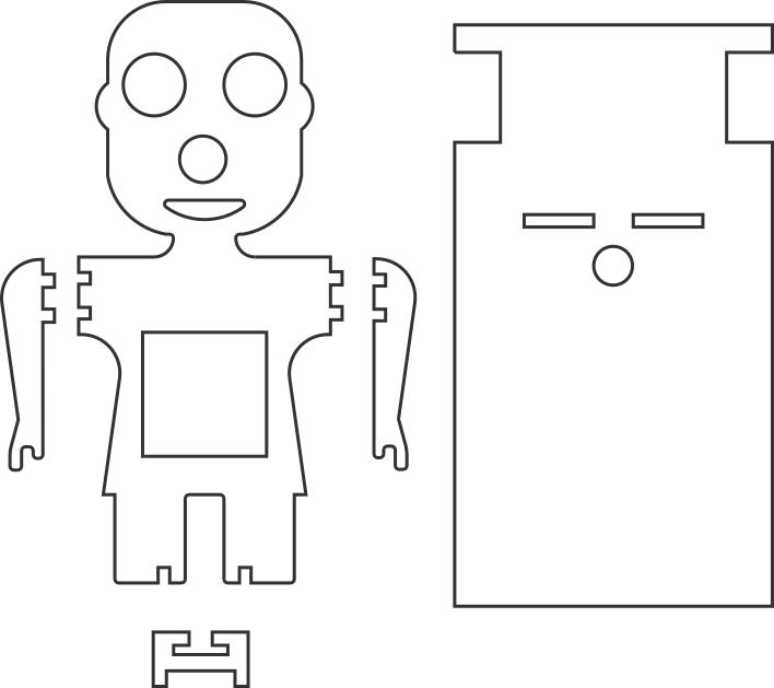
Based on this file, we need to ungroup objects and save them as separated files as:
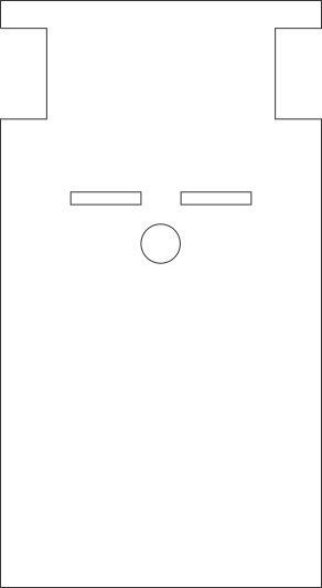
- Face (not including eyes, nose and mouth). Save it as “football_face.svg”

- Eyes, nose and mouth. Save it as “eye_nose_mouth.svg”

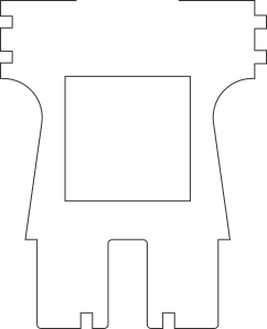
- Body. Save it as “football_body.png”
- Left and right arms. Save them is two separated files as “football_left_arm.svg” and “football_right_arm.svg”
![]()
![]()
- TCRT5000 Support. Save it as “TCRT5000_support.svg”

- Robot’s base. Save it as “grip_base.svg”
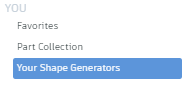
Now, in TinkerCAD, we need to select from “Our Shape Generators” and select “Extrusion”:
By default, we will see a cylinder as shown:
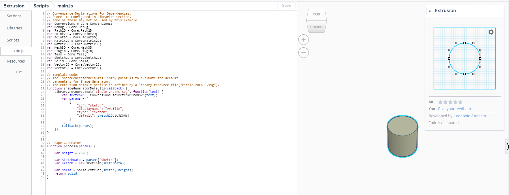
The aim is to modify the “main.js” script with code importing each of the shapes described before. In line 24 need to replace the filename with the one we want to generate, for instance “football_face.svg”. In line 42 we need to modify the object height by replacing “20.0” with “3.0”.
In addition to this, we need to remove the original file from “Resources” folder and import our file, in this case “football_face.svg”. In the “Settings” we can give some details about the shape we are generating such as the name and a description.
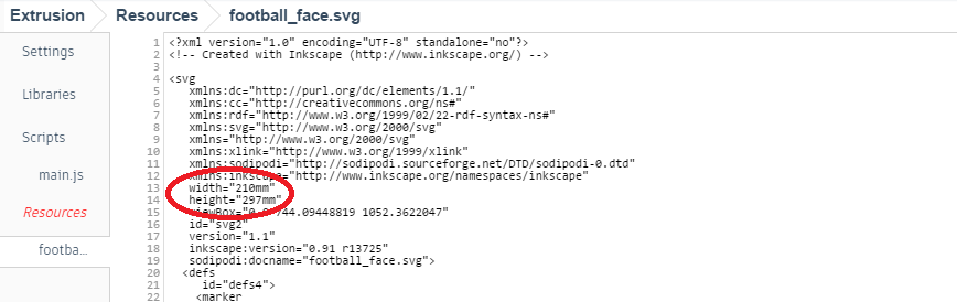
Inkscape generates a “SVG” file whose scale depends on the selected units when we imported the original “DXF” file (it was in pixels in order to be correct). It looks that, for some reason, in TinkerCAD, we also need to select the appropriate units for the shape generator. By default you will see that these uniters are in “mm”, so we have to replace them to “px”. This can be done in lines 13 and 14 of the “SVG” file, just below “Resources”, as shown:
Once all these steps have been completed, we can “Save” the shape and it will be available in your TinkerCAD menu.
Now, you are in position to customize to design, because it allows you to modify the shape.
As an alternative, you can always customize your design from the original “SVG” file in Inkscape and import that “SVG” file with the “Import” utility of TinkerCAD. The main difference is that, once imported, you want be able to modify the shape.
Following the described steps, you should get to the following result: