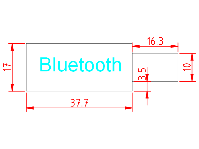
The purpose of this entry is to indicate necessary steps to create a CAD design, very basic, to represent the bluetooth module (HC-06) of the robot.
Our goal is to obtain a CAD design of the bluetooth module. Usually, this module will be located at the robot base, not requiring any supporting element, since we will glue it. For that reason, we can create this component in the auxiliary layer to help the design of the rest of the robot, but in any case we won’t cut material to support it.
The dimensions of the bluetooth module are shown next:

We will use the following template:
Select “Aux” layer and create a polyline with the following commands:
polyline
0,0
@37.7,0
@0,17
@-37.7,0
@0,-17
After that, we create another polyline with the following set of commands (also in the Auxiliary layer):
polyline
37.7,3.5
@16.3,0
@0,10
@-16.3,0
Finally, we can write a text using the “Text” tool at the left-side menu. Select the letter type and size as you consider appropriate (we have used Arial size 5).
Also, you can add some dimmensions using the “Dimension tools” at the Tool’s menu.
Here, you can download the DXF file with the complete solution:

