[:es]Aprende a utilizar el módulo de luz (seguilíneas). El robot DYOR utiliza este módulo para seguir líneas en el suelo (contraste entre blanco y negro). Principio de funcionamiento, diagramas de conexión y ejemplo de programación con Facilino y Arduino.
¿Cómo funciona?
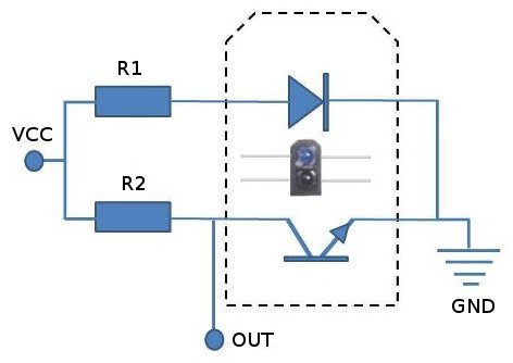
El módulo seguilíneas TCRT5000 es un sensor de que emite luz infrarroja, mediante un fotodiodo, que es reflejada por una superficie y captada por un fototransistor. El fototransistor es sensible a la luz recibida y genera una corriente en función dicha cantidad de luz que se transforma en voltaje eléctrico. En la configuración que se muestra a continuación, cuando el fototransistor es excitado con una fuente de luz, deja pasar corriente lo que hará que si medimos el voltaje justo entre la resistencia R2 y el fototransistor, la tensión tienda a 0V, mientras que si el fotodiodo no deja pasar la corriente, entonces la tensión que mediremos serán prácticamente Vcc.
Así pues, el nivel de señal analógica que proporciona el sensor dependerá por tanto de la cantidad de luz recibida. Esto puede depender de múltiples factores como la distancia de reflexión (distancia a la que se coloca el sensor con respecto a la superficie); el color de la superficie y la cantidad de luz infrarroja en el ambiente (dispone de un filtro para eliminar los efectos de la luz ambiental y de día, pero su uso en entornos exteriores está totalmente desaconsejado). Este tipo de sensores pueden utilizarse con diversos propósitos como la detección de objetos (presencia o no presencia) como un contacto de proximidad, ya que disponen de un corto alcance (máximo unos 15mm). En robótica, su principal utilidad es en aplicaciones del tipo seguilíneas en la que el sensor devolverá un valor distinto de función del color del suelo. Por ejemplo, si el suelo es de color negro el nivel de reflexión es muy bajo y el sensor devuelve un valor de señal elevado (lógica contraria). Si por el contrario el fondo del suelo es de color blanco el sensor apenas devuelve señal.
El módulo dispone además de un comparador analógico que lo que permite es establecer con un potenciómetro el nivel de referencia (de señal analógica) que queremos y por encima de ese nivel activará una señal digital, mientras que cuando esté por debajo de ese nivel la señal estará desactivada. Esto tiene sobretodo utilidad para su uso como contacto de proximidad.
Propiedades del sensor
- Rango de operación entre 0.5mm y 15mm.
- Longitud de onda de funcionamiento 950nm.
Conexión
El módulo TCRT5000 requiere de cuatro conexiones (si bien la salida digital no la utilizaremos):
- VCC: Alimentación. Conectar a los pines de +5V.
- GND: Masa. Conectar a los pines 0V (GND).
- DO: Salida digital. Se puede conectar a los pines digitales de Arduino
- AO: Salida analógica. Conectar a pines analógicos de Arduino.
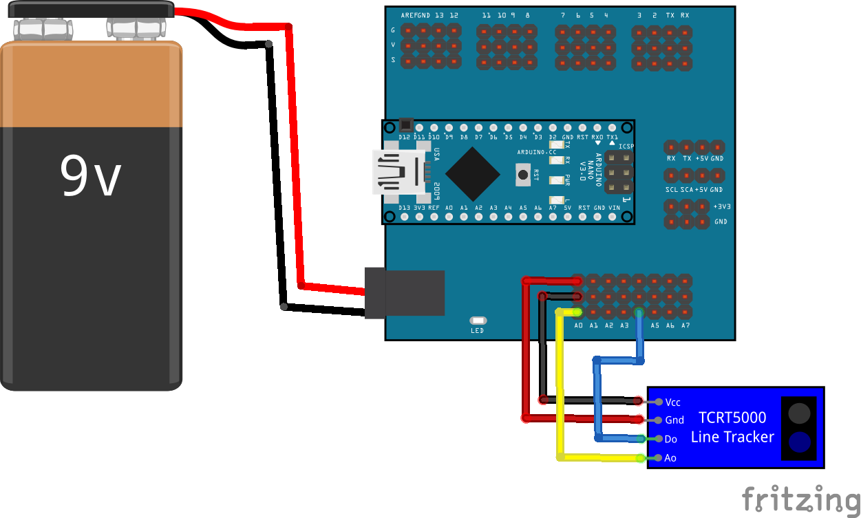
A continuación se muestra un ejemplo de conexión a Arduino Nano v3.0 con placa de expansión. La señal A0 se ha conectado al pin analógico A0 y la señal DO se ha conectado a uno de los pines de entrada analógico A4, pero que en realidad está configurado como pin digital. Esto se hace así para mostrar el hecho de que en realidad los pines analógicos pueden configurarse también como pines digitales normales. El el robot DYOR este pin normalmente no se utiliza y por este motivo ha preferido mostrarse el ejemplo de conexión de este pin en uno de los que habitualmente no se utilizan. Los pines VCC y GND se pueden conectar a cualquiera de las filas de alimentación y masa del módulo de expansión de entradas de Arduino Nano v3.0:
Aquí podéis descargar el fichero Fritzing:
Programación
A continuación se muestra un ejemplo de lectura de la señal analógica del sensor, un valor entre 0-1023 desde el punto de vista de la información devuelta, que se muestra por el puerto serie USB:
Aquí podéis descargar el fichero Facilino:
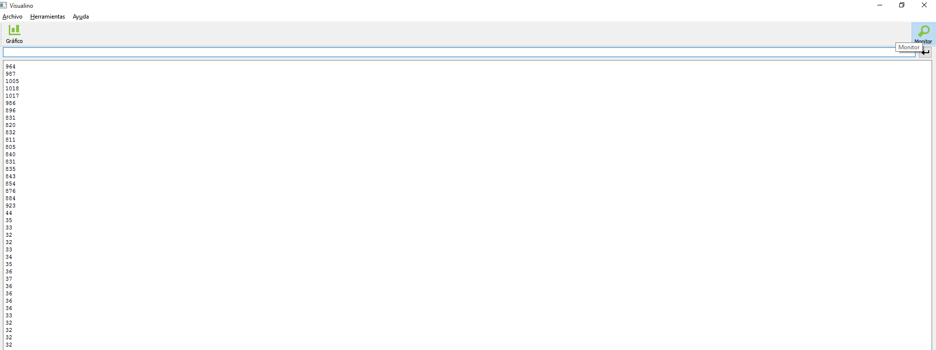
Podemos utilizar el monitor de la interfaz de Facilino para ver los valores devueltos por el sensor. En la siguiente captura de pantalla se muestra una clara diferencia entre los valores leídos cuando el sensor está apuntando a un objeto negro (valores por encima de 800) frente al caso en el que el sensor está apuntando a un objeto blanco (valores por debajo de 50).
A continuación se muestra un ejemplo de uso del módulo TCRT5000 con el valor analógico, pero que internamente divide en tres casos: blanco; gris; y negro. Cuando el nivel de luz está por debajo del 40% del valor medio de referencia entonces ejecutará las instrucciones del caso «blanco», mientras que si está entre el 40% y el 60% entonces ejecutará las instrucciones del caso «gris». En caso contrario, ejecutará las instrucciones del caso «negro». Para ello, el sensor debe primero calibrarse con los valores de «blanco» y «negro» en función de nuestras condiciones de trabajo. Se utiliza para este propósito dos instrucciones que sólo son necesarias llamarlas en el «setup» del programa. Estas instrucciones de calibración permiten establecer los valores para los cuales el sensor proporciona para cuando está en una zona blanca o en una zona negra. Previamente debemos haber anotado estos valores que el sensor nos devuelve en estos casos, por ejemplo, utilizando el programa de lectura analógica por el puerto serie anterior. En el código de ejemplo, si el caso detectado es blanco, negro o gris, el robot se moverá de una forma u otra utilizando las instrucciones de movimiento de la base (los servos SCR están conectados a los pines 9 y 5 respectivamente). Los valores tanto para la calibración, como para el movimiento de la base no tienen porqué coincidir con los que necesitéis para que os funcione correctamente el ejemplo ya que esto depende de los materiales y el entorno que utilicéis.
Aquí podéis descargar el fichero Facilino:
A continuación mostramos el ejemplo de código necesario para realizar un seguimiento de líneas. Al igual que en el ejemplo anterior, el programa requiere del uso de las instrucciones de calibración para su correcto funcionamiento. La principal diferencia con el ejemplo anterior es que la instrucción «seguidor de líneas» devuelve el valor de giro que deberíamos aplicar a la base. La cantidad devuelta está afectada por el valor de la ganancia, que cuanto más ganancia pongamos mayor será el efecto de corrección, pero puede presentar problemas oscilatorios con mayor frecuencia. La cantidad de giro se la indicamos a la base del robot. En este ejemplo, la velocidad lineal de avance es fija. Los valores introducidos para la ganancia, calibración y parámetros de movimiento de la base no tienen porqué coincidir con los que necesitéis para que os funcione.
Aquí podéis descargar el fichero Facilino:
[:en]Learn how to use the light module (linetracker). DYOR robot uses this module to track lines on the ground using the contrast (between black and white). Working principle, connection diagrams and programming examples with Facilino and Arduino.
How does it work?
TCRT5000 module emits an infrared light using a fotodiode that it’s reflected towards the surface. The light is reflected so that a fototransistor receives the amount of light reflected, which is in the end transformed into a voltage. The next image, when the fotodiode, when the fototransistor receives an amount of light will let the current flow so that the voltage will tend to 0V, while if no source light is receive, the fototransistor will be in ‘open circuit’, meaning that we will be measuring basically Vcc voltage.
The amount of light received might depend on many aspects, mainly with the distance to the surface and the color of the surface. It has a filter to filter out ambient light, but it’s use outdoors is not recommended, because the sensor becomes «blind» as an effect of infrared components of the sun light. This kind of sensors can also be used as obstacles detectors (with a very short-range about 15mm) and eventually they are used as contact-less switches. In robotics, their main application is to use them as line tracking module to distinguish the color of the ground (gray-scale). In particular, if the ground is dark or black, the reflection is very poor and the signal we measure is close to Vcc, while if the ground is white, then the amount of light reflected is high and the signal received will close to 0V.
The module has an analog comparator, meaning that with a potentiometer we can adjust a reference value we consider that the amount of light HIGH or LOW on its digital output. Therefore, this is useful when used as a digital switch.
Sensor Properties
- Measuring range 0.5mm and 15mm.
- Wave length 950nm.
Connection
The TCRT5000 uses four connections (although we won’t, usually, use the digital output):
- VCC: Power. Connect to +5V pins.
- GND: Ground. Connect to 0V (GND) pins.
- DO: Digital output. It can be connected to any digital pin of Arduino
- AO: Analog output. It must be connected to analog pins of Arduino.
Here we show a connection diagram using Arduino Nano v3.0. Signal A0 has been connected to analog pin A0, signal DO has been connected to pin A4 (as digital input). This is because, despite of the pin names, most of analog input pins can be used digital inputs/output too. Pins VCC and GND can be connected to any +5V and 0V pins of Arduino Nano v3.0, respectively:
Here, you can download the Fritzing diagram:
Programming
In this example, we show on the console the measured value, it should be between 0-1023 and change depending of the colour of the reflected surface:
Here, you can download Facilino’s code:
We can use Facilino’s console or Arduino IDE console to display the numbers. In the following image, we get values over 800 for black objects and under 50 for white objects.
Now, we will use the analog signal but it will be divided into three cases: white, gray and black. So when the amount of light is below the 40% of the reference light, we will consider the ‘white’ case. If the amount of light is between 40% and 60%, then the ‘gray’ case will be executed. Otherwise, the ‘black’ case will be executed. To adapt this to any situation, we need to calibrate the sensor first, by assigning the amount of level for ‘white’ and ‘black’ cases. This calibration procedure will be done during the setup. So, we need to annotate the values of ‘white’ and ‘black’ beforehand, using the code of the previous example.
In next example, we will use continuous rotation servos (SCR) connected to pins 9 and 5, respectively, to implement a line following routing using these three cases.
Here, you can download Facilino’s code:
Now, we show a different example to implement the line following application using Facilino’s code. The main difference with respect to the previous example is that the signal received will not be divided into three cases. We will directly use this signal and convert it into a rotation speed for the robot. There’s one only adjustable parameter which is the gain that we want to turn. The higher the gain the faster will converge to the line, but it can make the robot oscillating (rotating from one side to the other). The smaller the gain, the robot will turn slower, but at least won’t be oscillating, so it’s up to you. The distance of the infrared sensor to the wheels can significantly affect to. So if the distance is short, the robot is prone to oscillate. Again, we will need calibration values as before.
Here, you can download Facilino’s code:
[:]