[:es]
Aprende a utilizar un Servo. El robot DYOR utiliza los servos SG90 o TS90M para controlar el movimiento de sus pinzas o patas. Principio de funcionamiento, diagramas de conexión y ejemplo de programación con Facilino y Arduino o procesadores ESP.
¿Cómo funciona un Servo?
Un servo es un motor de corriente continua (CC) que dispone de la electrónica necesaria para posicionar el eje de giro mediante la generación de una señal de posición de pulso modulada (PPM). La gran mayoría de los servos utilizan un estándar en el que el periodo de la señal es de 20ms y se pueden mover desde su posición mínima con un ancho de pulso (típicamente de 0.5ms) hasta su posición máxima (típicamente de 2.5ms), pasando por su posición intermedia (normalmente son 1.5ms).

La especificación de la señal PPM a generar para su control viene del ámbito del radio control (RC), por este motivo, los controladores de motores sin escobillas (electronic speed control o ESC) típicamente utilizados en los drones también se controlan con señales PPM como la de los servos. En realidad la señal PPM, es una señal PWM (modulada por pulsos) con una frecuencia de 50Hz para el control de posición. Normalmente, el servomotor permite controlar la posición de un eje ya que dispone de un potenciómetro interno que permite realimentar dicha posición. Están además limitados mecánicamente con un tope, siendo 180º el máximo ángulo de giro de un servo. Existen modelos de servo que tienen otros ángulos de giro, con lo que es conveniente mirar las especificaciones del fabricante en cada caso.
Conexión de un Servo
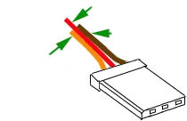
Los servos suelen utilizar un conector de 3 pines y dependiendo del tipo de fabricante existen diferentes variaciones en el conector y los colores empleados (la gran mayoría son compatibles entre ellos). Este es el tipo de conexión que utilizan los servos del robot DYOR y que se conecta directamente a la placa de expansión I/O de Arduino Nano.
Si por algún motivo nos equivocamos en la polaridad, al colocar el conector al revés, no se dañará ni el Servo ni el Arduino.
Control de un Servo
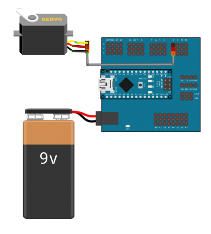
Para conectar un Servo a la placa de expansión de Arduino Nano debemos conectarlo a cualquiera de los pines digitales, mientras que para las placas ESP, es preferible utilizar los pines PWM.
Aquí podéis descargar el fichero Fritzing:
En Arduino un Servo se controla indicándole a la posición que queremos que se mueva, normalmente entre 0º y 180º. La posición 90º es justo en medio. En el siguiente ejemplo, se controlar un servo conectado al pin PWM 3 de Arduino Nano de forma que alternativamente se posiciona a 45º y a 135º.

A la hora de querer controlar un servo, es importante tener dos aspectos en consideración. Desde un punto de vista eléctrico, la señal de Servo de al menos 20ms entre dos comandos de movimiento consecutivos, con lo que al menos deberíamos esperar ese tiempo para ejecutar la siguiente instrucción de movimiento. Desde un punto de vista mecánico, el motor tarda un tiempo en alcanzar la configuración deseada que puede llegar a ser del orden del segundo, por tanto, si dos comandos de movimiento consecutivos están alternando entre dos posiciones distintas de forma que al servo servo no le da tiempo a alcanzar ni una ni otra, lo esperable es que esté en una zona intermedia con un comportamiento indefinido.
Aquí podéis descargar el fichero Facilino:
[:en]Learn how to use a Servo. DYOR robots use SG90 or TS90M servos to control movement of their grips or legs. Here we explain the working principle, connection diagrams and programming examples with Facilino and Arduino and ESP processors.
How does a Servo work?
A servo is a direct continuous (DC) motor with an electronic board that allows you to control the position of the rotating axis with a pulse-position modulated signal (PPM). Most of the servos use a standard signal of 20ms period, whose minimum position can be set with a pulse width of 0.5ms, its maximum position with a pulse width of 2.5ms and its intermediate position with a pulse width of 1.5ms.
PPM specifications come from radio control (RC) systems, for this reason, electronic speed control (ESC) board used for controlling the speed of brushless motors (typically used in drones) are also controlled with the same signal (with some additional protocols). Actually, we can see PPM as a particular case of pulse width modulation (PWM) with a frequency of 50Hz to control the position. The position of the servo motor is done in closed-loop, meaning that it measures the actual angle of the shaft with a rotational potentiometer and depending on the difference (error) of this angle and the actual reference, a current is injected onto the motor (to one direction or the opposite). There’s a mechanical limitation which prevents the motor to rotate further, typically the maximum angle range is 180º. There exists models with different ranges, so it is convenient to google for specification on each case.
Servo connection
Servos use a 3 pin connector. The cable colours and pinout depends on the manufacturer, although almost all are based on Hitachi connector and therefore they are compatible. This is the kind of connectors used also in many expansion boards, and particularly, Arduino Nano expansion board in DYOR robot. Fortunately, if we reverse the polarity of the connector, neither the Servo or Arduino will be damaged.
Servo control
In order to connect a Servo to Arduino expansion board, we can connected to any pin, while if we use ESP board it is preferable that they are connected to PWM pins.
Here you can download Fritzing diagram:
A servo can be controlled by indicating its position in degrees, a value between 0º and 180º. The position of 90º is the intermediate position. In this example, we are generating and positioning the servo, connected to pin 3, on alternate positions (45º and 135º) every 2 sec.
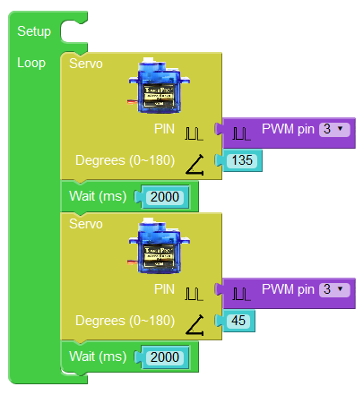
It is important to remark that, since the signal period of a servo is 20ms, the minimum time between two consecutive Servo instructions should be greater than 20ms. Therefore, we should always guarantee that this time has elapsed by introducing delays or controlling the periodicity of the code, otherwise it won’t work. From a mechanical point of view, we should also consider that servos have some «slow» dynamics, which means that we should not require to apply commands which require rotational speed over their specifications (i.e.: between 500º/sec and 600º/sec).
Here you can download Facilino code for the previous example:
[:]