In this post we show how to design DYOR robot step by step with TinkerCAD.
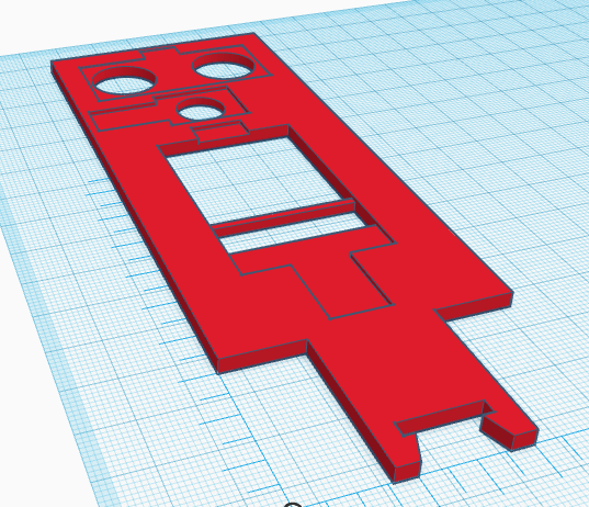
The aim of this post is to get the following 3D Design with TinkerCAD ready to be 3D Printed:
Here you can find some STL files we will need:
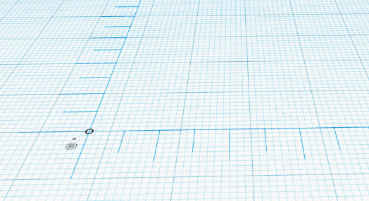
Let’s start by placing a ruler on the workplane (somewhere on the bottom-left corner):
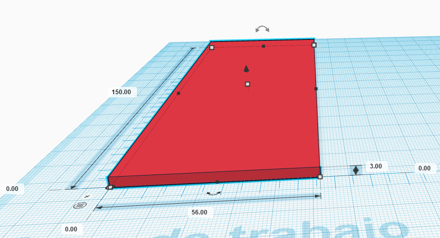
Now, create a cube (corresponding to the robot’s face) and place it at coordinates (0,0,0) and dimensions (56,150,3), long, wide, height, respectively.
Import “HC-SR04.stl” file and place it somewhere and rotate it 180º. Make it hole.
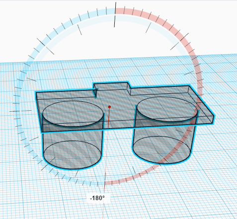
Now, place it at coordinate (5.5,124,-11) and group the shapes.
Import now the “Buzzer.stl” file and rotate it 180º and make it hole.
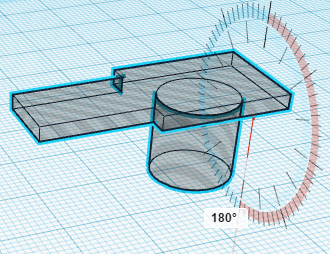
Now, place it at coordinate (1.55,107.6,-10) and group it.
Now, we will import “LED_Matrix_8x8.stl” file and rotate it 180º and make it hole.
Once rotated, place it at coordinate (12,33.3,-8) and group it (the image might not correspond if the LED Matrix does not include the MAX7219 chip).

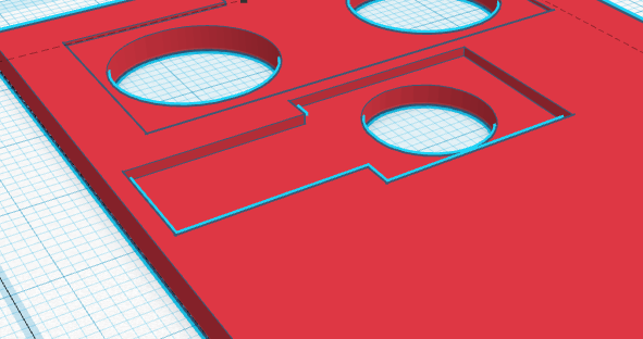
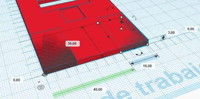
Now, we will create two hole cubes to remove part of the robot’s face at its bottom. The dimensions of the cubes are (16,30,3) and their coordinates (0,0,0) and (40,0,0). Once created, we can group them with the robot’s face.

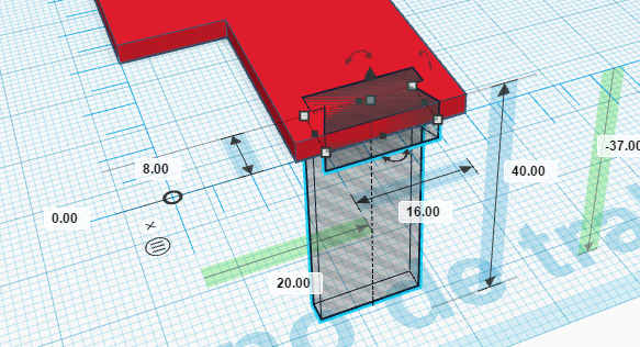
Finally, we must import the “TCRT5000.stl” file and make it hole. Place it at coordinate (20,0,-37) and group it.
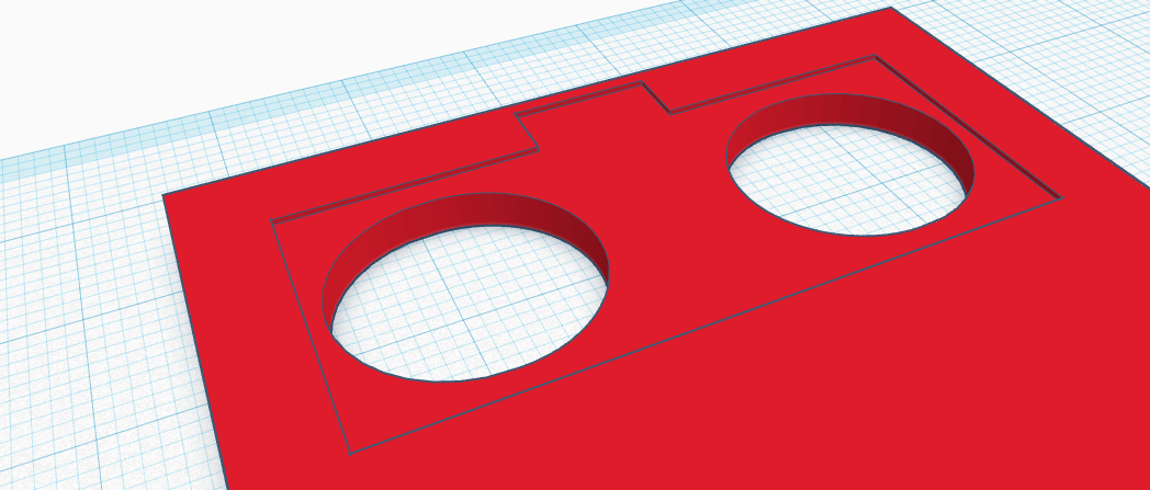
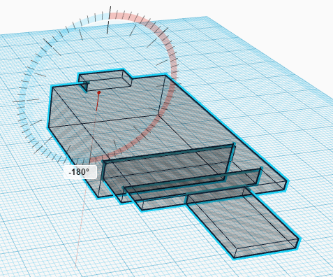
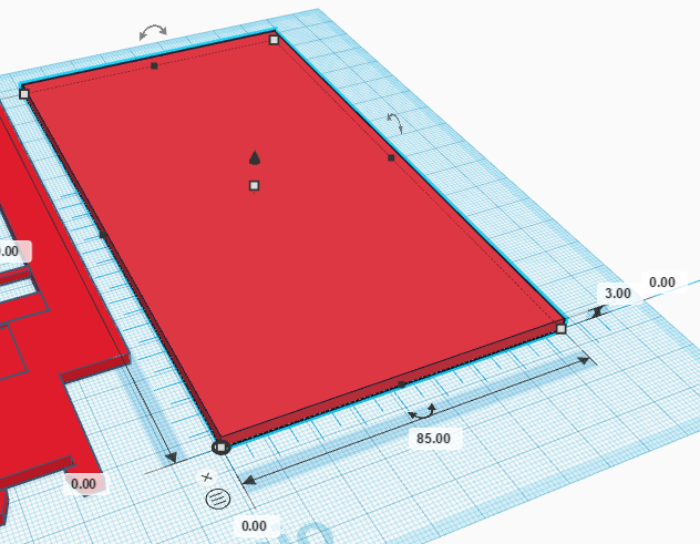
Now, move the ruler to the right and create a new cube of dimensions (85,150,3) and coordinate (0,0,0).
Import the “Servo.stl” files and make it hole and place it at coordinate (0,115,-14). Repeat this procedure to create the hole for the other servo and place it at coordinate () and group it.


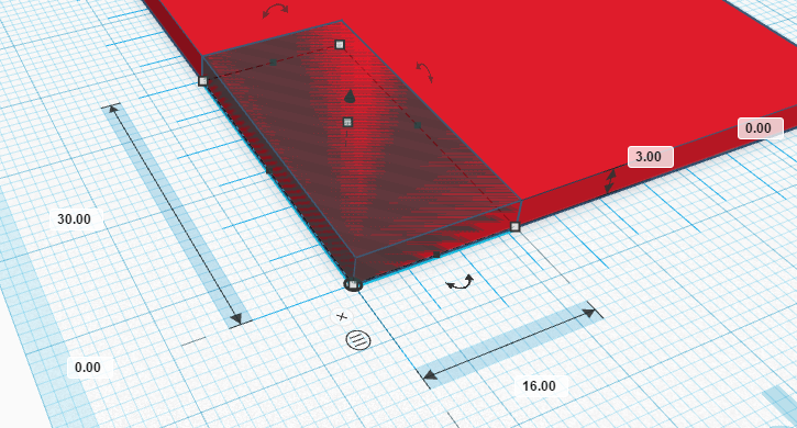
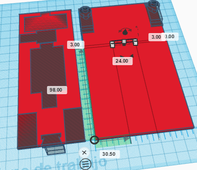
Finally, create another hole cube to fit the robot’s face within the robot base.Its size is (24,3,3) and it’s position is (30.5,98,0):
Group all objects of the robot base and you are ready to print your robot. Here you can find STL files with the solution: