[:es]Aprende a diseñar un modelo simplificado de la rueda loca para tu robot DYOR en TinkerCAD.
A continuación os mostraremos los pasos necesarios para diseñar la rueda loca para vuestro robot DYOR. El modelo a diseñar es un modelo simplificado para que fácilmente lo podáis hacer en el aula que permita generar posteriormente el sólido necesario para crear el diseño 3D completo del robot.
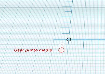
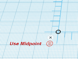
Comenzaremos arrastrando la regla a nuestro plano de trabajo (cualquier posición es buena) y seleccionamos «usar punto medio». Una vez seleccionado, cuando paséis el ratón por encima os debería aparecer «usar punto final», queriendo indicar que ya estáis utilizando el punto medio.
Ahora creamos un cilindro de dimensiones (25,25,13) y posicionamos su punto medio en la coordenada (0,0,12.5) con respecto al origen de la regla. Aumentamos el número de lados a 64 y establecemos giro de 90º con respecto a la cara lateral.


Ahora crearemos un tubo de dimensiones (22,22,5.5) y lo giraremos 90º con respecto a la cara lateral (la posición de momento no importa). El grosor del muro debe de ser 4.5, mientras que el parámetro rádio es de 10 (valor por defecto).


Una vez creado el tubo, vamos a copiar y pegar para tener otro tubo idéntico y los posicionamos en la coordenada (0,-5.5,12.5) el primero y en la coordenada (0,5.5,12.5) el segundo. Seleccionamos las tres formas y las agrupamos (CTRL+G).


Ahora crearemos una cuña de dimensiones (19,30,22), la posición no importa de momento, y la giraremos primero 180º con respecto a la cara lateral y después -90º con respecto a la cara superior.


Fijaros que tras girar la cuña hueca, las dimensiones de la cuña original son ahora (30,19,22). Ahora creamos una copia de la cuña y la posicionamos exactamente en el mismo lugar que la original pero su punto medio debe de estar 1mm por debajo. Modificamos el ancho para que sea de 17mm en vez de 19mm. Seleccionamos las dos cuñas y las agrupamos (CTRL+G) y posicionamos el nuevo objeto en la coordenada (15,0,23.5).


Finalmente creamos un cubo de dimensiones (38,38,1) y lo posicionamos en (16,0,35).

Opcionalmente, podéis añadir cuatro cilindros huecos de diámetro 2mm y altura 2mm en las siguientes posiciones (1.25,-14.75,35), (30.75,-14.75,35), (1.25,14.75,35) y (1.25,30,75,35). Podéis agrupas los cilindros huecos junto con el cubo que representa el soporte (CTRL+G).

Aquí podéis descargar el fichero STL con la solución:
 [:en]Learn how to design a Caster Wheel for your DYOR Robot with TinkerCAD.
Here we show the necessary steps to design a caster wheel for your DYOR robot. The aim is to design a simplified version of it that will help the assembly instructions. The proposed caster wheel is usually placed under the robot’s base. Here we show the expected result.
We will start by adding a ruler to any position (preferably on the bottom-left corner). Select ‘Use Midpoint’ (by default is in ‘EndPoint’ mode, so once in ‘MidPoint’ mode we should see ‘Use EndPoint’ when the mouse pointer is over it).
 Now, let’s create a cylinder of dimensions (25,25,13) and place it at coordinate (0,0,12.5) with respect to ruler’s origin. Increment the number of sides to 64 in the Shape properties and rotate it 90º as shown.
Now, create a tube with dimensions (22,22,5.5) and rotate it 90º as shown. Set the wall thickness to 4.5 and radius 10 (default value) in the Shape properties and make it hole.
Once created, we are going to copy the tube and place it at coordinate (0,-5.5,12.5) the first tube and second tube at coordinate (0,5.5,12.5). Select the cylinder and the tubes and group them.
Now, create a wedge with dimensions (19,30,22), the position is not important at the moment. Rotate the wedge 180º with respect to the lateral side and -90º with respect to the top side, as shown.
Now, create a copy of the original wedge and move it 1mm downwards. Set the width to 17mm instead of 19mm and make it hole. Select both objects and group them and place the new object at coordinate (15,0,23.5).
Finally, create a cube with dimensions (38,38,1) and place it at coordinate (16,0,35).
Optionally, you can create four cylinders of diameter 2mm and height 2mm at the following positions (1.25,-14.75,35), (30.75,-14.75,35), (1.25,14.75,35) y (1.25,30,75,35). Make them hole and group them together with the cube.
Here you can find the STL files with the solution:
[:]