[:es]Aprende a diseñar un modelo simplificado de la rueda que acopla al servo FS90R para tu robot DYOR en TinkerCAD.
A continuación os mostraremos los pasos necesarios para diseñar la rueda que acopla al servo FS90R para vuestro robot DYOR. El modelo a diseñar es un modelo simplificado para que fácilmente lo podáis hacer en el aula que permita generar posteriormente el sólido necesario para crear el diseño 3D completo del robot.
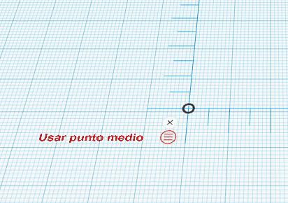
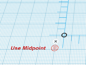
Comenzaremos arrastrando la regla a nuestro plano de trabajo (cualquier posición es buena) y seleccionamos «usar punto medio». Una vez seleccionado, cuando paséis el ratón por encima os debería aparecer «usar punto final», queriendo indicar que ya estáis utilizando el punto medio.
Ahora creamos un tubo de dimensiones (60,60,8) y posicionamos su punto medio en la coordenada (0,0,4) con respecto al origen de la regla. Aumentamos el número de lados a 64 y establecemos un grosor de muro de 2 (si el radio es 10, valor por defecto, representa un 20% de sus dimensiones, en este caso 48mm).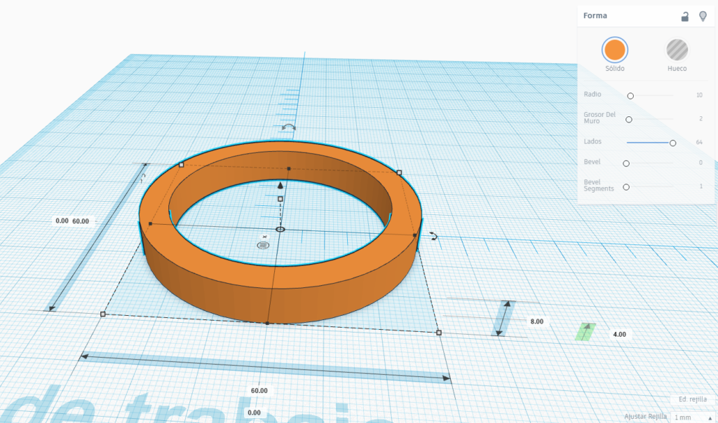
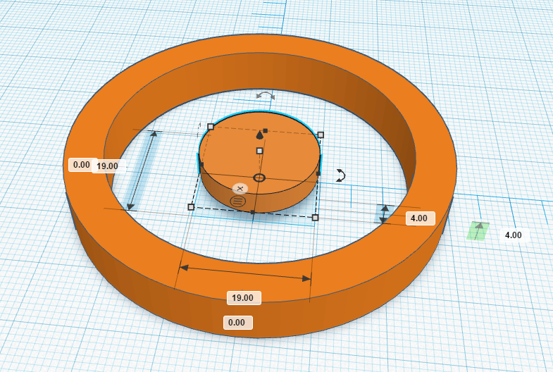
Ahora creamos un cilindro de dimensiones (19,19,4) en la posición (0,0,4) de 64 lados.
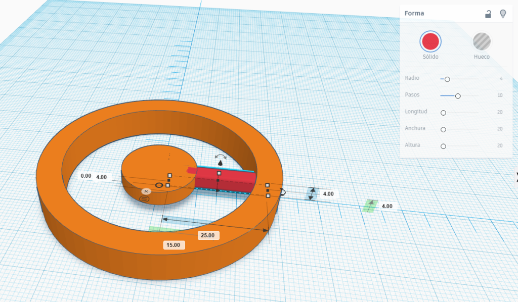
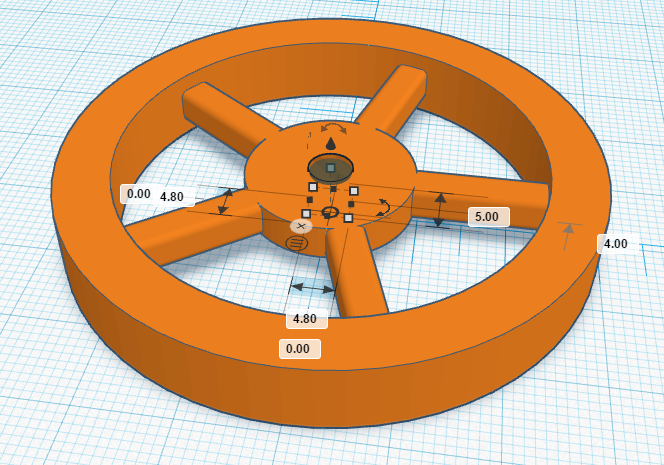
Para los radios de las ruedas, crearemos un cubo de dimensiones (25,4,4) en la posición (15,0,4). Para darle un aspecto redondeado utilizaremos un radio de 4 en sus propiedades de Forma.
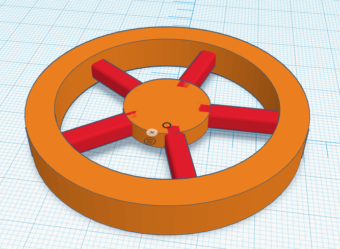
Para posicionar el resto de los radios debemos considerar el hecho de que están girados 72º entre ellos y la posición de su punto medio debe ser x=15*cos(angulo) e y=15*sin(angulo). Por tanto el procedimiento a seguir es, primero copiar y pegar el radio horizontal y girar la copia un ángulo de 72º, 144º, -72º y -144º con respecto a la cara superior, y calcular la posición de su punto medio según se ha indicado (es un problema trigonométrico sencillo!). A continuación se proporcionan los valores para los cuatro radios restantes.
72º -> (4.63,14.26)
144º ->(8.81,-12.13)
-72º -> (4.63,-14.26)
-144º -> (-8.81,-12.13)
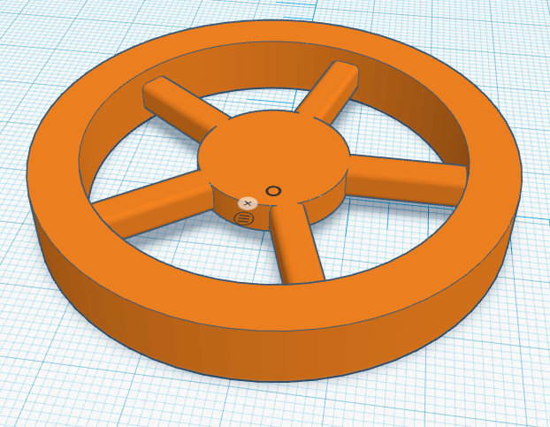
El resultado final debería ser como el que se muestra:
Observaréis que los radios hacen un efecto de visualización extraño al unirse con el cilindro del centro. Esto es debido a que ambos objetos tienen exactamente la misma altura y el programa no sabe cuál de los dos mostrar. Para solucionar esto, podemos agrupar todos los objetos creados hasta el momento. Para ello, los seleccionamos todos con el ratón y tecleamos CTRL+G (agrupar).
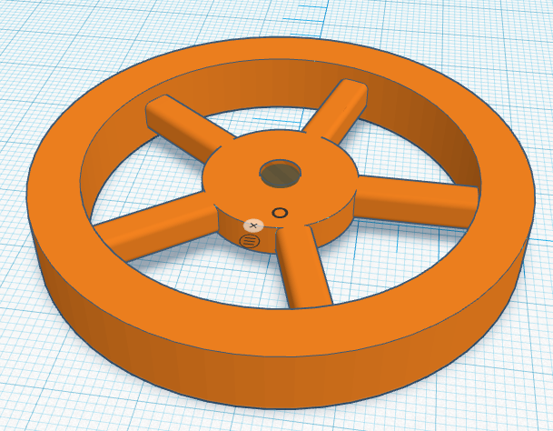
Finalmente, crearemos el orificio para acoplar el eje del servo. Es un cilindro hueco de dimensiones (4.8,4.8,5) en la posición (0,0,4).
Aquí podéis descargar el fichero STL con la solución:
 [:en]Learn how to design a simplified model of FS90R Wheel for your DYOR robot with TinkerCAD.
Here we will show necessary steps to design a simplified version of FS90R wheel for your DYOR robot with TinkerCAD. The model is intended to be as simple as possible with the purpose of being assembled with your complete robot design.
We will start by adding a ruler to our workplane (any position, but preferably on the bottom-left corner). Select ‘Use MidPoint’.
Now, create a tube of dimensions (60,60,8) and place it at coordinate (0,0,4) with respect to the rule position. Increase the number of sides to 64 and set the wall thickness to 2 (if the radius is 10, this basically means that the wall thickness is about 20% which corresponds to an inner hole of 48mm diameter).
Now, let’s create a cylinder of dimensions (19,19,4) at position (0,0,4) with 64 sides.
Spoke’s can be created with cubes of dimensions (25,4,4). The first of them at position (15,0,4). To round them we can set the radius property to 4.
The remainder of spokes are rotated 72º and the position of it’s intermediate point must be x=15*cos(angle) and y=15*sin(angle). Therefore, we need to copy and paste the first spoke and rotate it one of these angle values: 72º, 144º, -72º y -144º. Here you have the values of positions required for each case:
72º -> (4.63,14.26)
144º ->(8.81,-12.13)
-72º -> (4.63,-14.26)
-144º -> (-8.81,-12.13)
The expected result is shown in next figure:
Now, we can group the objects:
Finally, we can create a hole cylinder with dimensions (4.8,4.8,5) at position (0,0,4).
Here you can find the STL files with the solution:
[:]