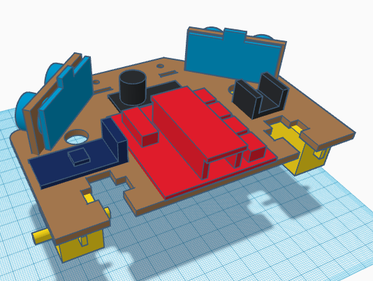
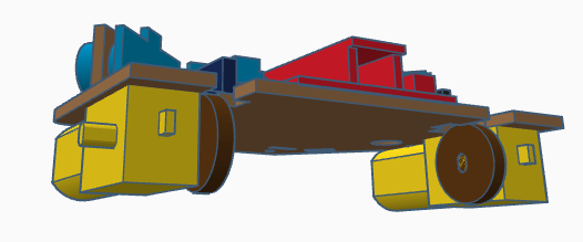
[:es]En esta entrada os mostramos el ensamblaje del robot DYOR Pro realizado con TinkerCAD y fabricado con corte láser.
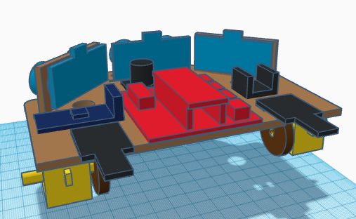
Componentes:
- Arduino Nano + Shield Arduino Nano I/O (rojo)
- Powerbank (naranja)
- Ultrasonido HC-SR04 (azul claro)
- Zumbador de sonido (negro)
- Servo SG90 (azul oscuro) en la pinza
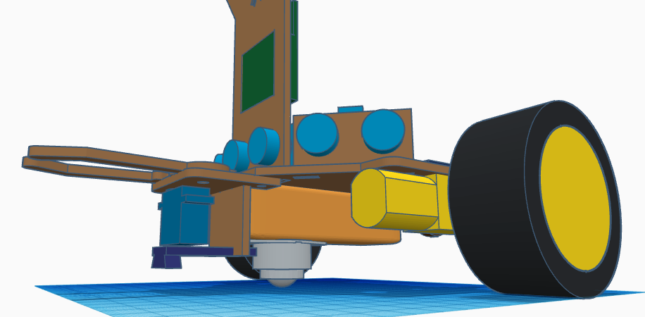
- Motor Smart Car (amarillo) en la base
- Bluetooth (azul oscuro)
- Seguilíneas TCRT5000 (azul oscuro)
- Rueda de bola (blanco)
- Ruedas Motores Smart Car (negro/amarillo)
- Matriz de LEDs (verde)
- Discos encoders para motores Smart Car (marrón)
- Encoders HC-020k (negro)
- Tira de 7 LEDs redonda (gris)
- Rodamiento MR52ZZ y tornillería.
Instrucciones
Para el montaje de este robot necesitaremos soldar algunos pines y cables. Es conveniente tener preparado previamente todos los componentes antes de pegarlos y por tanto, se recomienda realizar los pasos de soldadura al principio de todo (leer todas los pasos de las instrucciones previamente).
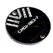
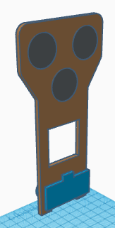
Empezaremos preparando las tiras de 7 LEDs de colores. Están compuesta por 3 tiras de LEDs que formarán los ojos y la boca del robot. Cada tira de LEDs tiene un pin de entrada IN y un pin de salida OUT. Además disponen de los pines de VCC y GND para la alimentación. Las tiras de LEDs se conectan en serie de forma que la salida de uno se debe conectar a la entrada del siguiente.
Empezaremos soldando unos cables a las tiras de 7 LEDs de colores. Deberemos cortar unos de los extremos de 3 cables DuPont, pelarlos y soldarlos a la tira de 7 LEDs del ojo derecho a los conectores VCC, GND e IN. La tira de 7 LEDs se posicionarán de forma que los conectores apuntan hacia arriba. Con otros 3 cables realizaremos las conexiones intermedias entre las otras tiras de 7 LEDs. De forma que la salida del ojo derecho la conectaremos a la entrada del ojo izquierdo. De nuevo, los conectores apuntan hacia arriba. De la salida de la tira del ojo izquierdo la conectaremos a la tira de 7 LEDs de la boca.
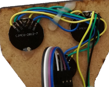
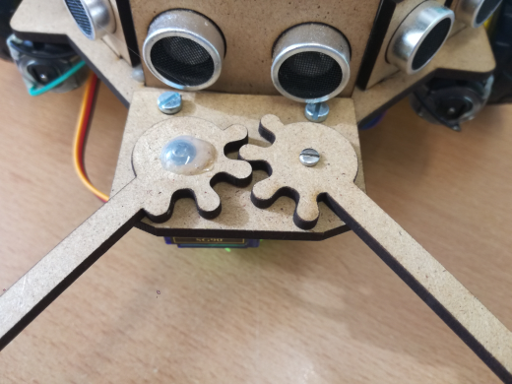
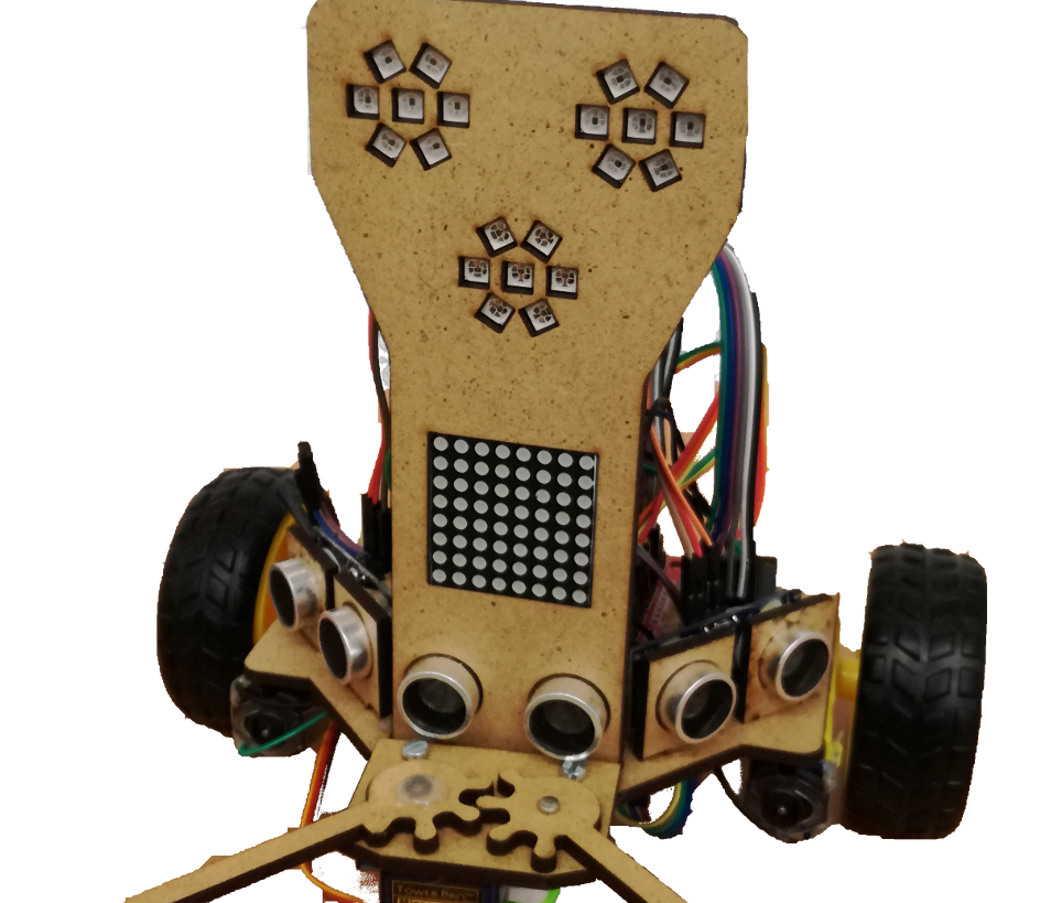
Una vez hemos soldado los cables, estamos en disposición de pegar las tiras de 7 LEDs al frontal del robot.
En la siguiente imagen se muestra un ejemplo real de cómo debería quedar:
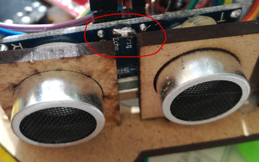
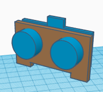
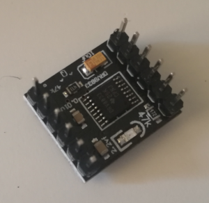
Los ultrasonidos deben ser modificados para que el pin de ECHO y TRIG se puedan controlar con un único pin de Arduino. Para ello, lo que haremos será soldar entre ambos pines tal y como se muestra en la imagen:
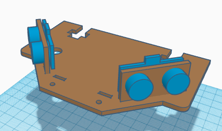
Ahora podremos pegar los ultrasonidos en sus correspondientes orificios. Uno de ellos se debe pegar al frontal del robot y los otros dos en sus propios soportes. Los conectores de los ultrasonidos deben quedar hacia arriba.
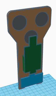
Conectar los cables de los ultrasonidos y pegar la matriz de LEDs al frontal del robot.
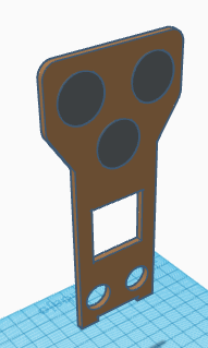
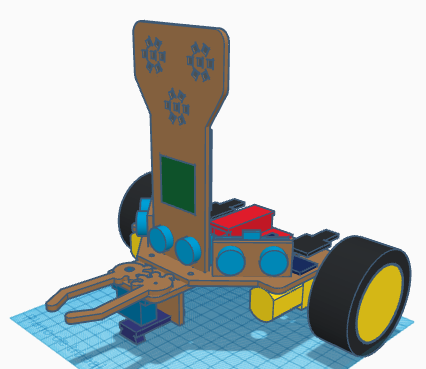
Para la pinza del robot debemos pegar el soporte de la pinza, el servo de posición SG90, el soporte del sensor TCRT5000 y el sensor TCRT5000 tal y como se muestra en la figura. El sensor TCRT5000 debe ir los más adelante posible, con objeto de que los cables no molesten posteriormente a la rueda loca. El potenciómetro del sensor puede colocarse entre el hueco que hay entre el servo SG90 y el soporte del sensor TCRT5000.
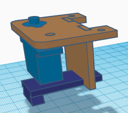
El dedo de la derecha se puede atornillar al eje del servo (no se requiere manilla) y en caso necesario pegar el tornillo al dedo. En el orificio de la izquierda del soporte de la pinza, colocaremos el rodamiento MR52ZZ asegurándonos que al pegarlo, sólo la parte exterior se queda pegada, quedando el eje interior libre. Utilizaremos el tornillo, arandelas y tuerca de M2 para fijar el dedo de la izquierda. En caso necesario, puede atornillarse la cabeza del tornillo y la tuerca al dedo y el soporte de la pinza, respectivamente.
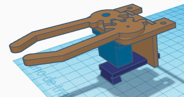
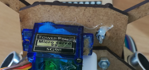
Nótese que el diseño de la pinza mostrada en la foto no coincide exactamente con el propuesto para el ensamblaje, sin embargo, el principio de funcionamiento es idéntico, ya que necesita atornillarse el servo e introducir el cojinete y pegarlo con un tornillo y tuerca.
Ahora pegaremos los ultrasonidos (con sus soportes) de la izquierda y derecha a la base del robot.
Los pines de driver DRV8833 requieren ser soldados, tal y como se muestra la figura:

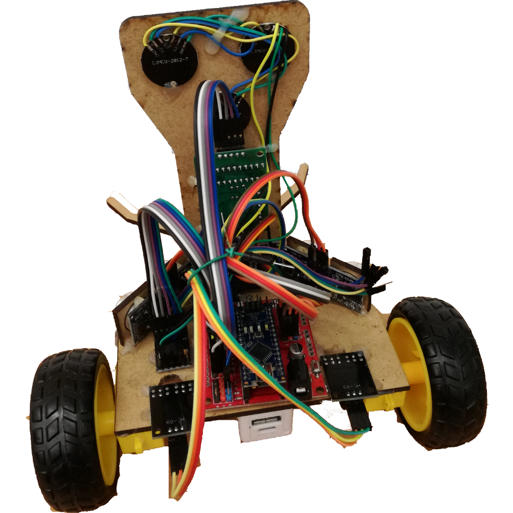
Posteriormente, pegaremos el zumbador, el driver DRV8833 de los motores, el módulo bluetooth y la placa de expansión de Arduino Nano a la base del robot.

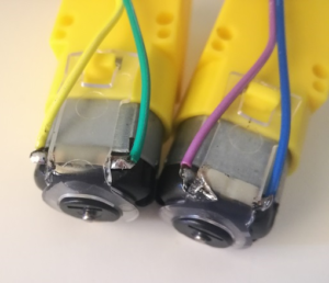
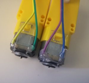
Posteriormente, pegaremos los motores en la parte inferior de la base del robot. Debemos soldar unos cables DuPont a los motores en los terminales metálicos que tiene (debemos cortar uno de los extremos del cable y pelarlo adecuadamente y enrollarlo al terminal del motor). Para evitar que la soldadura se dañe, es conveniente añadir un poco de pegamento una vez soldados.
Al colocar el motor, debemos asegurarnos que el eje del motor debe estar lo más atrás posible.
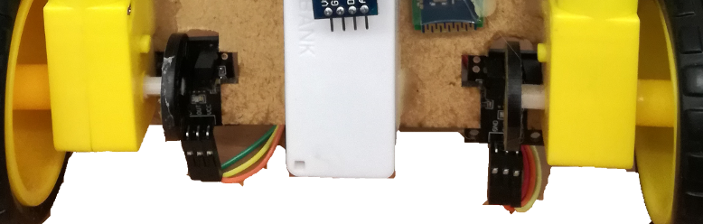
Insertar los discos codificadores en los ejes de cada uno de los motores, asegurándonos que están lo más centrados posibles con respecto al orificio de la base.
Pegar los módulos HC-020k de encoders del robot, asegurándonos que el disco está entre el sensor.
Colocar las ruedas del robot

Atornillaremos la pinza del robot a la base

Ahora pegaremos el frontal del robot a la base
Pasamos los cables de los motores, del servo SG90 y del sensor TCRT5000 los orificios de la base. Una vez hemos pasado los cables podremos pegar el Powerbank debajo de la base del robot y la rueda de bola al Powerbank (lo más adelante posible).
 [:en]In this entry we show the assembly of DYOR Pro robot with TinkerCAD and manufactured with laser cutting.
Components:
- Arduino Nano + Shield Arduino Nano I/O (red)
- Powerbank (orange)
- Ultrasound HC-SR04 (light blue)
- Buzzer (black)
- SG90 Servo (dark blue) en la pinza
- SmartCar Motor (yellow) en la base
- Bluetooth module (dark blue)
- TCRT5000 linetracker (dark blue)
- Ball wheel (white)
- SmartCar Motor Wheels (black/yellow)
- LEDs Matrix (green)
- SmartCar Encoder discs (brown)
- HC-020k Encoders (black)
- Round 7-LEDs strip (gray)
- MR52ZZ ball-bearing, screw and nut.
Instructions
Before assemblying this robot, we will need soldering of some pins. It is convinient to handle all this before assembly.
The round 7-LEDs strip needs soldering of input and output pins. We can simply use DuPont cables for this purpose. For instance, we can leave the female connector and cut the other end of it and solder it to the input connector of the left eye (on the back side corresponds to the Round 7-LEDs strip on the right). The connections between the left eye and the right eye must be also done by soldring some short cables from one to the other. Finally the connections from the right eye and the mouth will be also done by soldering some short cables among them. In summary, the LEDs strip must start by connecting the left eye (through its input connection), then the right eye and finally the mouth. Please, respect that order if you intend to use Facilino’s instructions.
Soldering is relatively easy. We simply need to connect the pins with VCC and GND from one board to the corresponding ones of the next board. The OUT pin of the left eye will be connected to the IN pin of the right eye. Also the OUT pin of the right eye will be connected to the IN pin of the mouth. The OUT pin of the mouth is unconnected.
Once everything is soldered, then we can glue them to the robot’s face.
Here we show an example of how it should be done:
Ultrasonic sensors, need to be «hacked» so that with one single line we can trigger and receive the echo. So the pins ECHO and TRIG must be short-circuited as shown:
Once done, we are in conditions of glueing them to their corresponding supports for the ones on the sides or to their corresponding holes in the robot’s face.
Connect the cables of the ultrasound sensors before glueing the LEDs matrix. The cables of the LEDs matrix will be connected from the top side.
Assembly of the robot’s grip requires to glue the SG90 servo on the corresponding hole. Please, note that to make the fingers co-plannar, only the rounded shape around the servo axis will be fitted on the hole, so that the finger is mostly in contact with the gripper surface. The sensor TCRT5000 is glued using its corresponding support, placing it as close as possible to the servo and with the potentiometer on the front-side of the support to avoid collisioning with the ball-wheel we will lately use.
The right finger must be screwed to the servo’s axis (no servo horn is required) and if it necessary, we can glue the screw to the finger. The small hole on the grip if for the ball bearing MR52ZZ, so it must be fitted inside. Then, we can simply use the screw and the nut to fit the left finger through the ball bearing. It is usually convinient to glue the nut to the grip to make sure that the finger does not fall apart.
Please, note that the picture above does not exactly correspond to the same grip design, but the principle is the same.
Now, we can glue the ultrasound sensors, with their supports on the robot’s base sides.
Also the pins of the DRV8833 require soldering, but this is quite straight-forward, as shown in next figure:
Once complete, we can glue the buzzer, the DRV8833 driver, the bluetooth module and the Arduino Nano expansion shield to the robot base.
Now, we can glue the motors to the robot’s base at the bottom of it. We also need to solder some cables to the motor electric terminals (it is convinient to use some glue after the pins have been soldered, because they can easily get disconnected with the cable is pulled).
Glueing the motors at the botoom of the base is quite easy, with the only consideration that the motor axis must be as rear as possible and as close as possible to the robot sides.
Once glued, we can put the encoder discs on the axis. Make sure that they are as centred as possible with respect to the hole on the base corresponding to the HC-020k sensors.
Now, place the HC-020k sensors as shown and make sure that the disc is correctly placed in the middle of the sensor.
Fix the robot wheels
Screw the gripper to the robot’s base.
and glue the robot’s face to the base
Pass all cables corresponding to the SG90 servo, TCRT5000 sensor, and motors through the holes. After that, we can glue the powerbank to the bottom side of the base (as close as possible to the TCRT5000 support). Glue the ball wheel at the bottom of the powerbank.
[:]