[:es]En esta entrada os mostramos el ensamblaje del robot DYOR WonderBot realizado con TinkerCAD y fabricado con corte láser
Componentes:
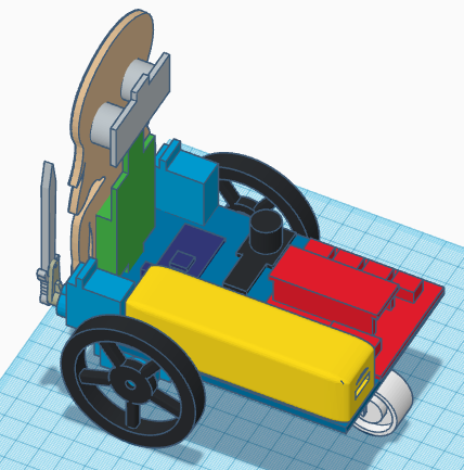
- Arduino Nano + Shield Arduino Nano I/O (rojo)
- Powerbank (amarillo)
- Ultrasonido HC-SR04 (gris)
- Zumbador de sonido (negro)
- Servos SG90 (azul claro) en la base
- Servos FS90R (azul claro) en la base
- Bluetooth (azul oscuro)
- Seguilíneas TCRT5000 (azul oscuro)
- Rueda loca (blanco)
- Ruedas FS90R (negro)
- Matriz de LEDs (verde)
Instrucciones
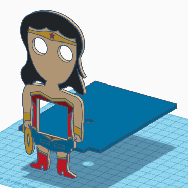
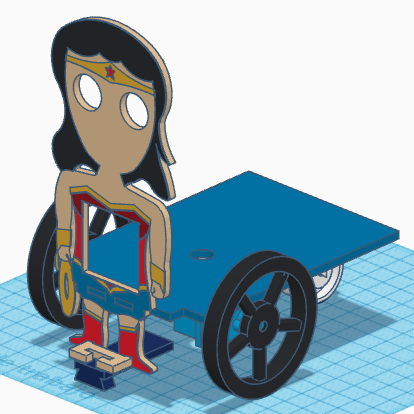
Colocar la pieza del frontal junto con la base y pegarlas.
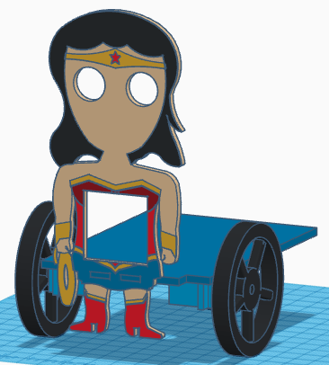
Pegar los servos FS90R a la base, estando el eje lo más atrás posible y atornillar las ruedas.
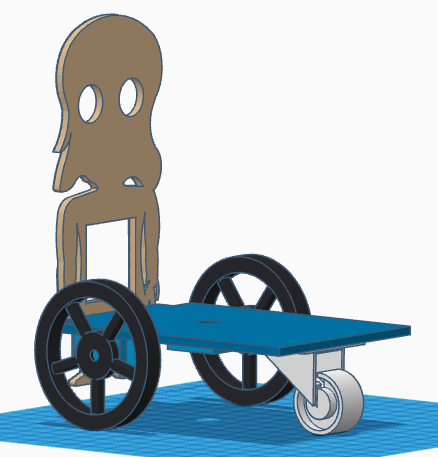
Pegar la rueda loca en la parte trasera de la base
Pegar el soporte del sensor TCRT5000 en los pies de forma horizontal y pegar el sensor al soporte (por debajo).
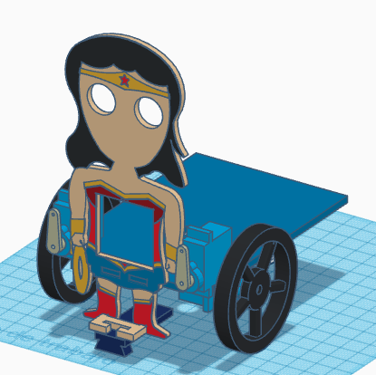
Pegar los servos SG90 en la parte delantera de la base con los ejes apuntando hacia delante y en la posición más cercana a las manos (el cable debe insertarse por las ranuras). Las manillas de los servos deben atornillarse a los ejes de forma que la posición indicada esté en 90º.
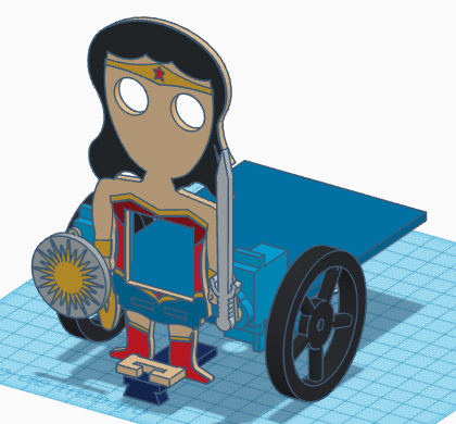
Ahora podremos pegar los accesorios, escudo y espada a las manillas de los servos SG90. La espada queda pegada a la manilla, mientras que el escudo lo podemos atornillar (y pegar, en caso necesario).
Pasar los cables, tanto de los servos FS90R y SG90 como del sensor TCRT5000 por el orificio que tiene la base. Una vez pasados los cables, podremos pegar la matriz de LEDs y el sensor de ultrasonidos al frontal, ambos con los cables de conexión por la parte superior.
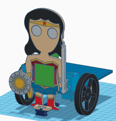
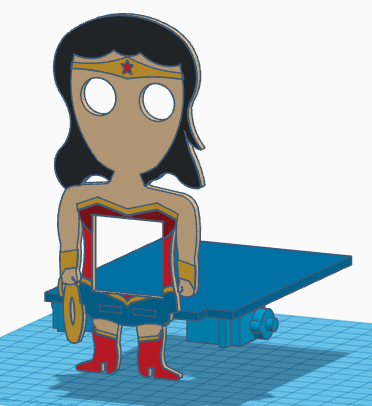
Pegar la electrónica de Arduino, el Powerbank, el módulo bluetooth y el zumbador de sonido a la base.
[:en]In this entry, we show the assembly of DYOR WonderBot with TinkerCAD and make with laser cutting
Components:
- Arduino Nano + Shield Arduino Nano I/O (red)
- Powerbank (yellow)
- Ultrasound HC-SR04 (grey)
- Buzzer (black)
- Servos SG90 (light blue) in the base
- Servos FS90R (light blue) in the base
- Bluetooth (dark blue)
- Linetracker TCRT5000 (blue)
- Caster wheel (white)
- FS90R wheels (black)
- LED Matrix (green)
Instructions
Glue both parts, the base and the frontal face.
Glue the FS90R servos to the base, the servo axis has to be as far as possible to the frontal face and screw the wheels to the servos.
Glue the caster wheel to the base
Glue the TCRT5000 support just below at the feet and glue the TCRT5000 sensor to the support (glue it so the sensor is below the feet horizontally).
Glue SG90 servos at the front of the base, with the axis pointing forward as close as possible to the hands (put the servo cable at the corresponding hole). Screw the servo horn so that the position of 90º is as shown in the Figure.
Now, glue the accessories, shield and sword, to the servo horns of SG90 servos. The sword must be glued, while the shield can be screwed to the horn (and glued if necessary).
FS90R and SG90 servo cables and TCRT5000 cables can be now pass through the base hole. After that, we can glue the LEDs matrix and ultrasound to the frontal face (both with cables pointing upwards).
Finally, glue the Arduino electronics, Powerbank, buzzer and Bluetooth module to the robot base.
[:]