[:es]En esta entrada se muestra cómo diseñar el robot DYOR con TinkerCAD paso a paso.
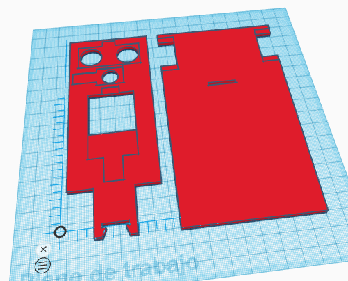
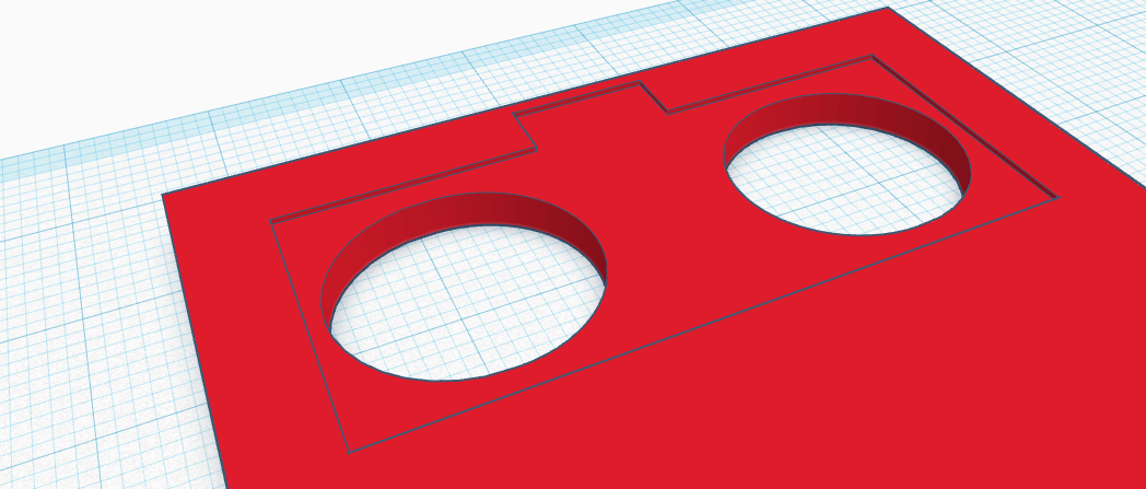
Nuestra propuesta para el diseño del robot DYOR en 3D es como se muestra a continuación, que está específicamente adaptada para la impresión 3D:
Para el diseño del robot utilizaremos los siguientes ficheros STL:
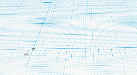
Comenzaremos arrastrando la regla a nuestro plano de trabajo (preferiblemente cerca de la esquina inferior izquierda).
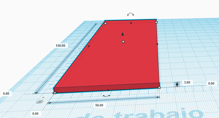
Ahora creamos un cubo (frontal del robot) y lo posicionamos con respecto al origen de la regla en la coordenada (0,0,0) y establecemos sus dimensiones (56,150,3), largo, ancho y alto, respectivamente.
Importar el fichero «HC-SR04.stl», posicionarlo en cualquier lugar, girarlo 180º con respecto a la cara frontal y hacerlo hueco.
Ahora lo posicionamos en la coordenada (5.5,124,-11) y lo agrupamos al frontal del robot.
Ahora importamos el fichero «Buzzer.stl», posicionarlo en cualquier lugar, girarlo 180º con respecto a la cara lateral y hacerlo hueco.
Una vez girado lo posicionamos en la coordenada (1.55,107.6,-10) y lo agrupamos con la pieza frontal.
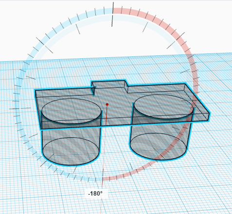
Ahora importamos el fichero «LED_Matrix_8x8.stl», posicionarlo en cualquier lugar, girarlo 180º con respecto a la cara frontal y hacerlo hueco.
Una vez girado lo posicionamos en la coordenada (12,33.3,-8) y lo agrupamos con la pieza frontal (el hueco generado por el chip de la matriz de LEDs puede que no esté si el fichero STL de la matriz de LEDs no lo incorpora).

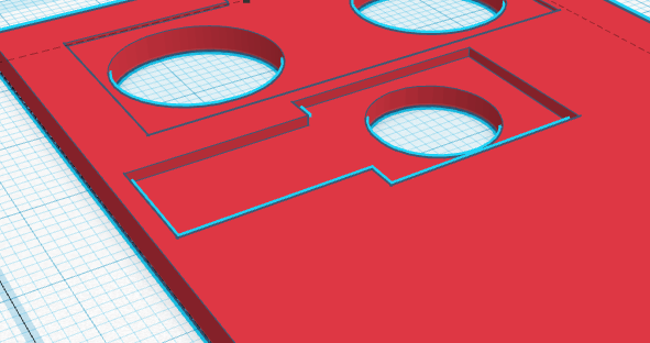
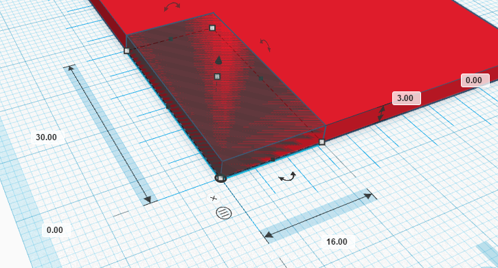
Ahora crearemos dos cubos huecos para eliminar parte de los laterales inferiores del frontal del robot. Las dimensiones son (16,30,3) y las posiciones son (0,0,0) y (40,0,0). Una vez creados los unimos con el resto de las piezas.

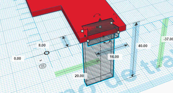
Finalmente, para terminar con la parte del frontal del robot, importamos el fichero «TCRT5000.stl», lo hacemos hueco y lo posicionamos en la coordenada (20,0,-37) y lo agrupamos con el resto de la pieza.
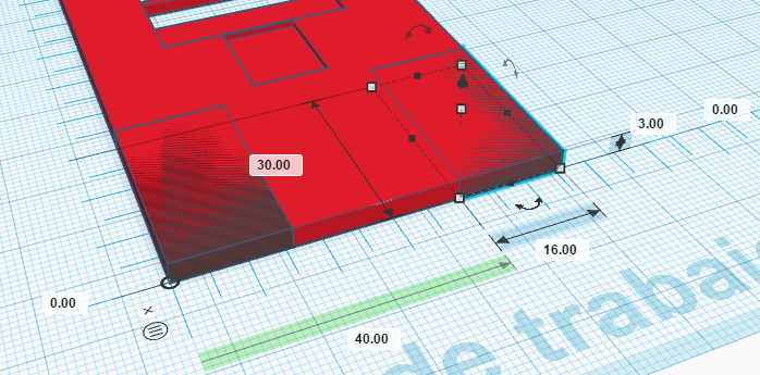
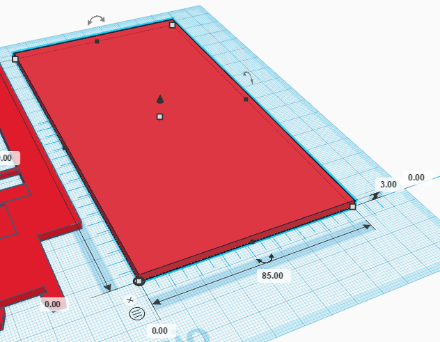
Para realizar la base del robot, moveremos la regla a un lugar donde tengamos espacio libre. Crear un cubo de dimensiones (85,150,3) y posicionarlo en la coordenada (0,0,0).
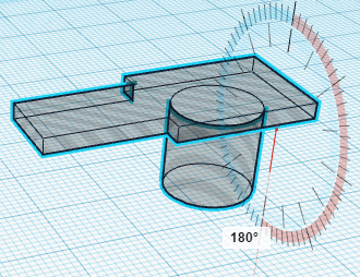
Ahora importamos el fichero «Servo.stl», lo hacemos hueco y lo posicionamos en la coordenada (0,115,-14). Hacemos lo mismo para el otro servo y lo posicionamos en la coordenada () y agrupamos los servos con el objeto de la base del robot.


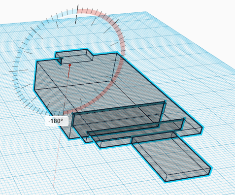
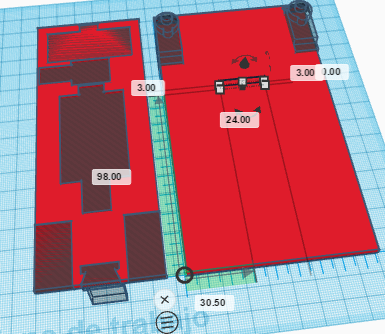
Finalmente, crearemos un orificio (ranura) para que pase el frontal del robot.La ranura es un cubo hueco de dimensiones (24,3,3), posicionado en la coordenada (30.5,98,0):
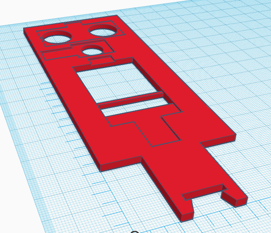
Agrupar los objetos y ya tenéis las piezas del robot. Aquí podéis descargar el fichero STL con la solución:
[:en]In this post we show how to design DYOR robot step by step with TinkerCAD.
The aim of this post is to get the following 3D Design with TinkerCAD ready to be 3D Printed:
Here you can find some STL files we will need:
Let’s start by placing a ruler on the workplane (somewhere on the bottom-left corner):
Now, create a cube (corresponding to the robot’s face) and place it at coordinates (0,0,0) and dimensions (56,150,3), long, wide, height, respectively.
Import «HC-SR04.stl» file and place it somewhere and rotate it 180º. Make it hole.
Now, place it at coordinate (5.5,124,-11) and group the shapes.
Import now the «Buzzer.stl» file and rotate it 180º and make it hole.
Now, place it at coordinate (1.55,107.6,-10) and group it.
Now, we will import «LED_Matrix_8x8.stl» file and rotate it 180º and make it hole.
Once rotated, place it at coordinate (12,33.3,-8) and group it (the image might not correspond if the LED Matrix does not include the MAX7219 chip).
Now, we will create two hole cubes to remove part of the robot’s face at its bottom. The dimensions of the cubes are (16,30,3) and their coordinates (0,0,0) and (40,0,0). Once created, we can group them with the robot’s face.
Finally, we must import the «TCRT5000.stl» file and make it hole. Place it at coordinate (20,0,-37) and group it.
Now, move the ruler to the right and create a new cube of dimensions (85,150,3) and coordinate (0,0,0).
Import the «Servo.stl» files and make it hole and place it at coordinate (0,115,-14). Repeat this procedure to create the hole for the other servo and place it at coordinate () and group it.
Finally, create another hole cube to fit the robot’s face within the robot base.Its size is (24,3,3) and it’s position is (30.5,98,0):
Group all objects of the robot base and you are ready to print your robot. Here you can find STL files with the solution:
[:]