QCAD is a CAD design tool simple to use and free (at least its basic functionality, there are versions that limit working time to 15 minutes, but other versions allow you to work continuously, but after 15 minutes disable some advanced features).
We will assume from this point that you have the version 3.3.0 installed (some things may be slightly modified in future versions). You can download here the version that we use:
Laser Cutting
The ultimate purpose of designing with QCAD is mainly laser cutting. We must know some basic concepts of laser cutting technology to be able to design our pieces. A laser beam allows to cut certain types of materials or silkscreen (make a superficial etching). The procedure is usually quite simple, because from a DXF file (AutoCAD format) you can generate code for the laser cutting Machine (CNC code). In general, some considerations should be considered
- Size of the griddle (if we want to optimize the space)
- Effective diameter of the laser
- Minimum separation
- Material to be used
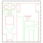
Since the objective is that each one can make its own design, we will limit the workspace to 150x160mm2. It is advisable to leave 1 mm of separation to the sides, although this depends on whether we will join several designs, because it could coincide that both make the most of the surface and is not required of this space. The material to be used is plywood (3 mm thickness), so if you have to make holes for two pieces to fit, you must have this information into account. The effective diameter of the laser is less than 0.2 mm, which implies that if we want to avoid certain gaps, you should draw 0.1 mm apart from the specifications. The truth is that taking into consideration the effective diameter of the laser is what should theoretically be done, but in practice, since we are going to stick a large part of the components, it will not be necessary. In addition to this, a good design must always try to optimize costs and therefore, polylines must be used, instead of separate drawing entities, because otherwise the cost can increase significantly. There are different layers of work: cutting, surface etching and annotations. According to our design and manufacturing goal, we must move some elements from one layer to another.
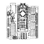
2D design of the components and DYOR robot
Below we show the entries related to the QCAD design:
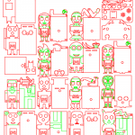
2D Robot Designs with Laser Cutting in 3mm
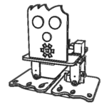
QCAD Design of DYOR bPED

CAD templates for customizing DYOR robot
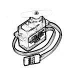
QCAD Design of a 360º servo
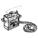
QCAD Design of a Servo

Diseño QCAD del módulo de luz TCRT5000
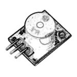
Diseño QCAD del módulo de sonido (zumbador)
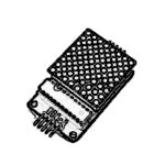
QCAD Design of the 8×8 LEDs matrix
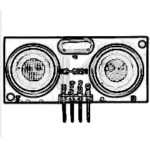
QCAD Design of ultrasound sensor HC-SR04

QCAD Design of the USB Powerbank

QCAD Design of the bluetooth module HC-06
2D QCAD Design of DYOR robot